DM330012 Microchip Technology, DM330012 Datasheet - Page 17
DM330012
Manufacturer Part Number
DM330012
Description
55T2293
Manufacturer
Microchip Technology
Datasheet
1.DM330012.pdf
(30 pages)
Specifications of DM330012
Core Architecture
DsPIC
Core Sub-architecture
DsPIC33
Silicon Core Number
DsPIC33E
Kit Contents
DsPIC33E Or PIC24E USB Starter Kit Board, USB Cable
Available stocks
Company
Part Number
Manufacturer
Quantity
Price
Company:

Part Number:
DM330012
Manufacturer:
MICROCHIP
Quantity:
12 000


© 2010-2011 Microchip Technology Inc.
2.2.5
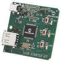
Push button switches (SW1, SW2 and SW3) provide the following functionality:
• SW1: Active-low switch connected to RD6
• SW2: Active-low switch connected to RD7
• SW3: Active-low switch connected to RD13
The switches do not have any debounce circuitry and require the use of software
debounce techniques. When idle, the switches are pulled high (+3.3V). When pressed,
they are grounded.
2.2.6
The LEDs (LED1, LED2 and LED3) are connected to PORT D of the processor:
• LED1: Active-high LED connected to RD0
• LED2: Active-high LED connected to RD1
• LED3: Active-high LED connected to RD2
The corresponding PORT D pins must be configured as digital outputs and set high in
order to turn on the LEDs.
2.2.7
The installed DSC or MCU has an 8 MHz crystal (Y3) connected to it. This crystal is
used by the microcontroller’s Primary Oscillator. Use of the external crystal is required
in order to develop USB applications, as the USB specification dictates a frequency tol-
erance of ± 0.25% for full speed. Non-USB applications can use the internal oscillators
if preferred. The starter kit also has provisions for an external Secondary Oscillator
(Y2); however, the crystal for this oscillator is not populated.
The PIC24FJ256GB106 device is independently clocked and has its own 12 MHz
crystal (Y1).
2.2.8
The dsPIC33E or PIC24E USB Starter Kit includes a 120-pin modular expansion
interface (Application Board Connector J3) on its bottom side. This allows the board to
be optionally used in conjunction with other Microchip development boards such as the
I/O Expansion Board or the Multimedia Expansion Board (MEB), thereby extending the
functionality provided by the starter kit.
TABLE 2-1:
Starter Kit Connector
Application Board Connector
Switches
LEDs
Oscillator Options
120-pin Modular Expansion Connector
STARTER KIT CONNECTOR PART NUMBERS
Connector
FX10A-120P/12-SV1(71)
FX10A-120S/12-SV(71)
HIROSE Electric P/N
DS51936B-page 17
Related parts for DM330012
Image
Part Number
Description
Manufacturer
Datasheet
Request
R

Part Number:
Description:
Manufacturer:
Microchip Technology Inc.
Datasheet:
Part Number:
Description:
Manufacturer:
Microchip Technology Inc.
Datasheet:
Part Number:
Description:
Manufacturer:
Microchip Technology Inc.
Datasheet:
Part Number:
Description:
Manufacturer:
Microchip Technology Inc.
Datasheet:
Part Number:
Description:
Manufacturer:
Microchip Technology Inc.
Datasheet:
Part Number:
Description:
Manufacturer:
Microchip Technology Inc.
Datasheet:
Part Number:
Description:
Manufacturer:
Microchip Technology Inc.
Datasheet:
Part Number:
Description:
Manufacturer:
Microchip Technology Inc.
Datasheet: