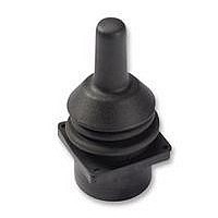
3140RQ0124 APEM Components, 3140RQ0124 Datasheet - Page 3

3140RQ0124
Manufacturer Part Number
3140RQ0124
Description
84R1057
Manufacturer
APEM Components
Datasheet
1.3140RAK6125.pdf
(10 pages)
Specifications of 3140RQ0124
No. Of Axes
2
Supply Voltage Max
5V
Centre Voltage
2V
Switch Terminals
Connector
Handle Style
Skirted
Svhc
No SVHC (20-Jun-2011)
Handle Type1
Skirted
Terminal Type
Connector
Rohs Compliant
Yes
3000 SERIES - CONTACTLESS JOYSTICKS
CONFIGURATIONS & OUTPUTS
FIVE CONFIGURATION OPTIONS
When considering a 3000 Series the first decision is what type of outputs are needed for your application. There are five output
configurations offered as standard:
1. For general purpose applications operating on a 5V supply, this configuration provides one proportional output per axis,
a centre tap reference and a separate centre detect output. Customers may choose from a wide range of possible options including
different: voltage outputs (gains), handles, bezels and limiters.
2. For low voltage applications the 3000 Series may be specified to operate with a supply of 3.3V. This version is offered as
standard with +/-50% gain, yielding a voltage span from 0V (South) to 3.3V (North). No centre tap or centre detect outputs are
offered, however customers may continue to determine their preference of limiter, handle & bezel.
3. For safety critical applications requiring a second set of dual redundant signals, the 3000 Series may be configured as two
“electrical” joysticks in one mechanical package. This joystick operates on 5V and provides two outputs per axis of the same
polarity for example Y, Y & X, X. The second set of outputs are accurate to the first within +/-5% of the power supply. The power
supply and centre tap for the secondary outputs are also completely independent. No centre detect functionality is offered with this
configuration. Customers may continue to choose their preference of voltage outputs (gains), limiter, handle or bezel.
4. As per option 3, but the secondary outputs are of inverse polarity to the primary wipers for example X, -X & Y, -Y. The first and
second outputs can be summed and compared to Centre Tap to verify that the joystick is operating correctly.
5. Operating on a 5V supply the 3000 Series may be selected with a variety of PWM output options. For more details on the type
of outputs available please refer to Apem.
Note: Configurations 3 and 4 are available as standard for one or two axes joysticks. For three axes joysticks in either
configuration, please refer to Apem.
ADDITIONAL OUTPUT INFORMATION
CENTRE DETECT (CD)
Where selected, (configuration 1 types) the output on this additional cable will be 0V whilst the joystick is inactive. Should either the
X or Y outputs change outside of the centre tolerance, indicating that the joystick has been operated, the centre detect signal will
switch to 5V. Within the joystick this output is pulled high by a 2K2 resistor and is decoupled by a 100nF capacitor to 0V. This output
is designed for use in applications requiring an enable/disable signal that is separate from the main wipers. It is not recommended
for use as a safety feature or a method of “person-present “ detection.
CENTRE TAP REFERENCE (CT)
Where selected, (configurations 1, 3 and 4) the joystick also outputs a centre reference voltage that is set at 50% (+/-1%) of the
supply voltage. This output can be used to check the integrity of the power supply applied to the joystick. A reading on this output,
outside of the specified tolerance suggests a problem with the power supply to the joystick. The other purpose of this output is to act
as a reference equal to the voltage output when the lever is at centre. Measuring the voltage outputs relative to CT rather than 0V
eliminates inaccuracies created by variation in supply voltage.
GAIN OPTIONS
The voltage output on the wipers, at full scale deflection is determined by the gain. The gain is expressed as a percentage of the
voltage supplied. Therefore (assuming a 5V supply) a joystick specified with +/- 25% gain would yield 1.25V at South, 2.5V at
centre and 3.75V at North. A range of gain options are available as standard for configurations 1, 3 and 4. All joysticks are
supplied pre-set and no further calibration is needed throughout the lifetime of operation.
OUTPUT IMPEDANCE
The voltage outputs at centre and at each end of travel are specified across an infinite load, with no current flowing. The output
impedance specified in the electrical specification should be taken into account when designing a system. Load resistance of less
than 10K Ohms is not recommended.
www.apem.com
3
Note: The company reserves the right to change specifications without notice.


