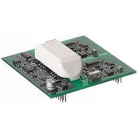
SKYPER 32 PRO SEMIKRON, SKYPER 32 PRO Datasheet - Page 10

SKYPER 32 PRO
Manufacturer Part Number
SKYPER 32 PRO
Description
16M0274
Manufacturer
SEMIKRON
Datasheet
1.SKYPER_32_PRO.pdf
(18 pages)
Specifications of SKYPER 32 PRO
Device Type
IGBT
Module Configuration
Half Bridge
Peak Output Current
15A
Input Delay
1.2µs
Output Delay
1.2µs
Supply Voltage Range
14.4V To 15.6V
No. Of Pins
20
Rohs Compliant
Yes
Short Pulse Suppression (SPS)
This circuit suppresses short turn-on and off-pulses of incoming signals. This way the IGBTs are protected against spurious
noise as they can occur due to bursts on the signal lines. Pulses shorter than 625ns are suppressed and all pulses longer
than 750ns get through for 100% probability. Pulses with a length in-between 625ns and 750ns can be either suppressed or
get through.
Failure Management
A failure caused by PRIM_nPWRFAIL_IN, under voltage protection, dynamic short circuit detection or external error input
will force PRIM_HALT_OUT into HIGH state (not ready to operate). The IGBTs will be switched off (IGBT driving signals set
to LOW) and switching pulses from the controller will be not transferred to the output stage. Connected and switched off
IGBTs remain turned off. At the same time an internal timer with a time constant of 3s is started. If no failure, caused by
PRIM_nPWRFAIL_IN or under voltage protection is present anymore, a time of 3s after failure detection is passed and also
TOP and BOT input signals are set to the LOW level for a period of minimum t
operate and switching pulses are transferred to the output stage. If PRIM_HALT_OUT is HIGH state, the external error input
is not monitored. A present failure signal at external error input during PRIM_HALT_OUT in HIGH state is again detected
after a reset signal and first transfer of TOP and BOT switching pulses to the output stage.
SKYPER™ 32PRO R
TOP / BOT Input
Pulse pattern – SPS
Pulse Pattern Failure Management
10
2007-01-19 – Rev03
A capacitor is connected to the input to obtain high noise
immunity. This capacitor can cause for current limited line drivers
a little delay of few ns, which can be neglected. The capacitors
have to be placed as close as possible to the driver interface.
Propagation delay of the driver, interlock dead time
and switching time of the IGBT chip has to be taken
into account (not shown in the pulse pattern).
pERRRESET
> 9µs, the driver core is ready to
© by SEMIKRON


