SKYPER 32 PRO SEMIKRON, SKYPER 32 PRO Datasheet - Page 3
SKYPER 32 PRO
Manufacturer Part Number
SKYPER 32 PRO
Description
16M0274
Manufacturer
SEMIKRON
Datasheet
1.SKYPER_32_PRO.pdf
(18 pages)
Specifications of SKYPER 32 PRO
Device Type
IGBT
Module Configuration
Half Bridge
Peak Output Current
15A
Input Delay
1.2µs
Output Delay
1.2µs
Supply Voltage Range
14.4V To 15.6V
No. Of Pins
20
Rohs Compliant
Yes


Application and Handling Instructions
Further application support
Latest information is available at http://www.semikron.com. For design support please read the SEMIKRON Application
Manual Power Modules available at http://www.semikron.com.
General Description
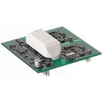
The SKYPER™ 32PRO core constitutes an interface between IGBT modules and the controller. This core is a half bridge
driver. Functions for driving, potential separation and protection are integrated in the driver. Thus it can be used to build up a
driver solution for IGBT modules.
Features of SKYPER™ 32PRO
SKYPER™ 32PRO R
3
Please note:
Unless otherwise specified, all values in this technical explanation are typical values. Typical values are the average values expected in
large quantities and are provided for information purposes only. These values can and do vary in different applications. All operating
parameters should be validated by user’s technical experts for each application.
Repeated turn-on of the IGBT into a short circuit with a high frequency may destroy the device.
these inputs. Therefore, control signal over-voltages exceeding the above values have to be avoided.
Please provide for static discharge protection during handling. As long as the hybrid driver is not completely assembled,
the input terminals have to be short-circuited. Persons working with devices have to wear a grounded bracelet. Any
synthetic floor coverings must not be statically chargeable. Even during transportation the input terminals have to be
short-circuited using, for example, conductive rubber. Worktables have to be grounded. The same safety requirements
apply to MOSFET- and IGBT-modules.
Any parasitic inductances within the DC-link have to be minimised. Over-voltages may be absorbed by C- or RCD-
snubbers between main terminals for PLUS and MINUS of the power module.
When first operating a newly developed circuit, SEMIKRON recommends to apply low collector voltage and load current
in the beginning and to increase these values gradually, observing the turn-off behaviour of the free-wheeling diode and
the turn-off voltage spikes generated across the IGBT. An oscillographic control will be necessary. Additionally, the case
temperature of the module has to be monitored. When the circuit works correctly under rated operation conditions,
short-circuit testing may be done, starting again with low collector voltage.
It is important to feed any errors back to the control circuit and to switch off the device immediately in failure events.
The inputs of the hybrid driver are sensitive to over-voltage. Voltages higher than V
The connecting leads between hybrid driver and the power module should be as short as possible (max. 20cm), the
driver leads should be twisted.
Two output channels
Integrated potential free power supply for secondary side
Short Pulse Suppression (SPS)
Under Voltage Protection (UVP) primary & secondary
Under Voltage Reset (UVR)
Drive interlock (dead time) top / bottom (DT) adjustable
Dynamic Short Circuit Protection (DSCP) by V
switch off
Soft Turn-Off (STO)
Halt Logic Signal (HLS)
Failure Management
External Error Input
DC bus voltage up to 1200V
Coated with varnish
CE
2007-01-19 – Rev03
monitoring and direct
SKYPER™ 32PRO
S
+0,3V or below -0,3V may destroy
© by SEMIKRON
Related parts for SKYPER 32 PRO
Image
Part Number
Description
Manufacturer
Datasheet
Request
R


Part Number:
Description:
IC, DUAL IGBT DRIVER, PCB-60
Manufacturer:
SEMIKRON
Datasheet:

Part Number:
Description:
SKYPER 32PRO
Manufacturer:
SEMIKRON [Semikron International]
Datasheet:

Part Number:
Description:
Semikron International [IGBT Module]
Manufacturer:
Semikron International
Datasheet:
Part Number:
Description:
Semikron International [3-phase bridge rectifier + brake chopper + 3-phase bridge inverter]
Manufacturer:
Semikron International
Datasheet:
Part Number:
Description:
Semikron International [3-phase bridge rectifier + brake chopper + 3-phase bridge inverter]
Manufacturer:
Semikron International
Datasheet:
Part Number:
Description:
Semikron International [3-phase bridge rectifier + brake chopper + 3-phase bridge inverter]
Manufacturer:
Semikron International
Datasheet:
Part Number:
Description:
Semikron International [Power MOSFET Modules]
Manufacturer:
Semikron International
Datasheet:
Part Number:
Description:
Semikron International [Thyristor / Diode Modules]
Manufacturer:
Semikron International
Datasheet:
Part Number:
Description:
Semikron International [SEMIPACK1 Thyristor / Diode Modules]
Manufacturer:
Semikron International
Datasheet:
Part Number:
Description:
Semikron International [Thyristor / Diode Modules]
Manufacturer:
Semikron International
Datasheet: