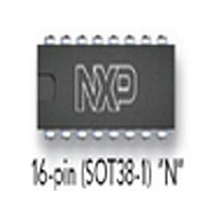
TDA9830 NXP Semiconductors, TDA9830 Datasheet - Page 4

TDA9830
Manufacturer Part Number
TDA9830
Description
Manufacturer
NXP Semiconductors
Datasheet
1.TDA9830.pdf
(15 pages)
Specifications of TDA9830
Lead Free Status / Rohs Status
Compliant
Available stocks
Company
Part Number
Manufacturer
Quantity
Price
Part Number:
TDA9830
Manufacturer:
PHILIPS/飞利浦
Quantity:
20 000
Company:
Part Number:
TDA9830 PHI
Manufacturer:
AD
Quantity:
600
Company:
Part Number:
TDA9830/V1
Manufacturer:
Philips
Quantity:
546
Company:
Part Number:
TDA9830T
Manufacturer:
LINEAR
Quantity:
2 127
Part Number:
TDA9830T
Manufacturer:
PHILIPS/飞利浦
Quantity:
20 000
Company:
Part Number:
TDA9830T/V1
Manufacturer:
PHILIPS
Quantity:
5 200
Part Number:
TDA9830V1
Manufacturer:
PHILIPS/飞利浦
Quantity:
20 000
Philips Semiconductors
PINNING
FUNCTIONAL DESCRIPTION
Sound IF input
The sound IF amplifier consists of
three AC-coupled differential
amplifier stages each with
approximately 20 dB gain. At the
output of each stage is a multiplier for
gain controlling (
distribution gain control). The overall
control range is approximately 6 to
+60 dB and the frequency response
( 3 dB) of the IF amplifier is
approximately 6 to 70 MHz. The
steepness of gain control is
approximately 10 mV/dB.
IF AGC
The automatic gain control voltage to
maintain the AM demodulator output
signal at a constant level is generated
by a mean level detector. This
AGC-detector charges and
discharges the capacitor at pin 3
controlled by the output signal of the
AM-demodulator compared to an
internal reference voltage. The
June 1994
IFIN
n.c.
C
C
n.c.
AMOUT
AMIN
AFOUT
EXTIN
SWITCH
V
MUTE
GND
V
n.c.
IFIN
p2
p1
AGC
REF
TV sound AM-demodulator and audio source switch
SYMBOL
current
PIN
10
12
13
14
15
16
11
1
2
3
4
5
6
7
8
9
sound IF differential input signal
not connected
AGC capacitor
REF voltage filtering capacitor
not connected
AM demodulator output
input signal (from AM) to audio switch
output signal from audio switch
input signal (from external) to audio switch
switch input select control
supply voltage +12 V (alternative)
mute control
ground (0 V)
supply voltage +5 to +8 V
not connected
sound IF differential input signal
maximum charge/discharge current is
approximately 5 A. This value in
combination with the value of the
AGC capacitor and the AGC
steepness determines the lower
cut-off audio frequency and the
THD-figure at low modulation
frequency of the whole
AM-demodulator. Therefore a large
time constant has to be chosen which
leads to slow AGC reaction at IF level
change. To speed up the AGC in case
of IF signal jump from low to high
level, there is an additional
comparator built in, which can provide
additional discharge current from the
AGC capacitor up to 5 mA in a case of
overloading the AM demodulator by
the internal IF signal.
AM-demodulator
The IF amplifier output signal is fed to
a limiting amplifier (two stages) and to
a multiplier circuit. However the limiter
output signal (which is not any more
AM modulated) is also fed to the
multiplier, which provides AM
DESCRIPTION
4
demodulation (in phase
demodulation). After lowpass filtering
(f
buffering, the demodulator output
signal is present at pin 6. The AM
demodulator operates over a wide
frequency range, so that in
combination with the frequency
response of the IF amplifier
applications in a frequency range
from approximately 6 MHz up to
70 MHz are possible.
Audio switch
This circuit is an operational amplifier
with three input stages and internal
feedback network determining gain
(0 dB) and frequency response
(f
stages are connected to pin 7 and pin
9, the third input stage to an internal
reference voltage. Controlled by the
switching pins 10 and 12, one of the
three input stages can be activated
and a choice made between two
different AF signals or mute state.
The selected signal is present at
g
g
400 kHz) for carrier rejection and
700 kHz). Two of the input
Fig.2 Pin configuration.
Product specification
TDA9830


