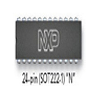
S87C751-4N24 NXP Semiconductors, S87C751-4N24 Datasheet - Page 8

S87C751-4N24
Manufacturer Part Number
S87C751-4N24
Description
Manufacturer
NXP Semiconductors
Datasheet
1.S87C751-4N24.pdf
(24 pages)
Specifications of S87C751-4N24
Cpu Family
87C
Device Core
80C51
Device Core Size
8b
Frequency (max)
16MHz
Interface Type
I2C/UART
Program Memory Type
EPROM
Program Memory Size
2KB
Total Internal Ram Size
64Byte
# I/os (max)
19
Number Of Timers - General Purpose
1
Operating Supply Voltage (typ)
5V
Operating Supply Voltage (max)
5.5V
Operating Supply Voltage (min)
4.5V
Instruction Set Architecture
CISC
Operating Temp Range
0C to 70C
Operating Temperature Classification
Commercial
Mounting
Through Hole
Pin Count
24
Package Type
PDIP
Lead Free Status / Rohs Status
Not Compliant
Philips Semiconductors
EXPLANATION OF THE AC SYMBOLS
Each timing symbol has five characters. The first character is always
‘t’ (= time). The other characters, depending on their positions,
indicate the name of a signal or the logical status of that signal. The
designations are:
1998 May 01
80C51 8-bit microcontroller family
2K/64 OTP/ROM, I
C – Clock
D – Input data
H – Logic level high
L – Logic level low
Q – Output data
T – Time
V – Valid
X – No longer a valid logic level
Z – Float
V
CC
0.45V
–0.5
Maximum I
2
C, low pin count
I
Notes 5 and 6 refer to DC Electrical Characteristics.
0.2 V
CC
0.2 V
Typical I
CC
(mA)
CC
CC
values taken at V
– 0.1
+ 0.9
22
20
18
16
14
12
10
CC
8
6
4
2
Figure 1. External Clock Drive
values taken at V
Figure 2. I
4MHz
t
CHCL
CC
8MHz
CC
t
8
FREQ
CLCX
max and worst case temperature.
vs. FREQ
CC
12MHz
= 5.0V and 25 C.
t
CLCL
16MHz
t
CLCH
MAX ACTIVE I
TYP ACTIVE I
MAX IDLE I
TYP IDLE I
t
CHCX
SU00298
CC
CC
CC
6
CC
6
5
5
SU00297
83C751/87C751
Product specification


