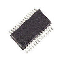
LM4835MTX National Semiconductor, LM4835MTX Datasheet - Page 18

LM4835MTX
Manufacturer Part Number
LM4835MTX
Description
Manufacturer
National Semiconductor
Datasheet
1.LM4835MTX.pdf
(28 pages)
Specifications of LM4835MTX
Operational Class
Class-AB
Audio Amplifier Output Configuration
2-Channel Stereo
Output Power (typ)
1.5W
Audio Amplifier Function
Headphone/Speaker
Total Harmonic Distortion
0.3@8Ohm@1W%
Single Supply Voltage (typ)
3/5V
Dual Supply Voltage (typ)
Not RequiredV
Power Supply Requirement
Single
Rail/rail I/o Type
No
Power Supply Rejection Ratio
74dB
Single Supply Voltage (min)
2.7V
Single Supply Voltage (max)
5.5V
Dual Supply Voltage (min)
Not RequiredV
Dual Supply Voltage (max)
Not RequiredV
Operating Temp Range
-40C to 85C
Operating Temperature Classification
Industrial
Mounting
Surface Mount
Pin Count
28
Package Type
TSSOP
Lead Free Status / Rohs Status
Not Compliant
Available stocks
Company
Part Number
Manufacturer
Quantity
Price
Company:
Part Number:
LM4835MTX
Manufacturer:
ERICSSON
Quantity:
5
Part Number:
LM4835MTX
Manufacturer:
NS/国半
Quantity:
20 000
Company:
Part Number:
LM4835MTX/NOPB
Manufacturer:
NS
Quantity:
13 929
Part Number:
LM4835MTX/NOPB
Manufacturer:
NS/国半
Quantity:
20 000
www.national.com
Application Information
tected on pin 11, the bridge output amplifiers are enabled.
The beep signal is amplified and applied to the load con-
nected to the output amplifiers. A valid beep signal will be
applied to the load even when MUTE is active. Use the input
resistors connected between the BEEP IN pin and the stereo
input pins to accommodate different beep signal amplitudes.
These resistors are shown as 200kΩ devices in Figure 2.
Use higher value resistors to reduce the gain applied to the
beep signal. The resistors must be used to pass the beep
signal to the stereo inputs. The BEEP IN pin is used only to
detect the beep signal’s magnitude: it does not pass the
signal to the output amplifiers. The LM4835’s shutdown
mode must be deactivated before a system alert signal is
applied to BEEP IN pin.
MICRO-POWER SHUTDOWN
The voltage applied to the SHUTDOWN pin controls the
LM4835’s shutdown function. Activate micro-power shut-
down by applying V
the LM4835’s micro-power shutdown feature turns off the
amplifier’s bias circuitry, reducing the supply current. The
logic threshold is typically V
MODE FUNCTION
The LM4835’s MODE function has two states controlled by
the voltage applied to the MODE pin (pin 4). Mode 0, se-
lected by applying 0V to the MODE pin, forces the LM4835
to effectively function as a "line-out," unity-gain amplifier.
Mode 1, which uses the internal DC controlled volume con-
trol, is selected by applying V
sets the amplifier’s gain according to the DC voltage applied
to the DC VOL CONTROL pin. Prevent unanticipated gain
behavior by connecting the MODE pin to V
not let pin 4 float.
MUTE FUNCTION
The LM4835 mutes the amplifier and DOCK outputs when
V
LM4835 will amplify a system alert (beep) signal whose
magnitude satisfies the BEEP DETECT circuitry. Applying
0V to the MUTE pin returns the LM4835 to normal, unmated
operation. Prevent unanticipated mute behavior by connect-
ing the MUTE pin to V
DD
is applied to pin 5, the MUTE pin. Even while muted, the
SHUTDOWN
Logic High
Logic Low
Logic Low
Logic Low
Logic Low
PIN
DD
TABLE 1. Logic Level Truth Table for SHUTDOWN, HP-IN, and MUX Operation
to the SHUTDOWN pin. When active,
DD
or ground. Do not let pin 5 float.
DD
DD
to the MODE pin. This mode
/2. The low 0.7µA typical
Logic High
Logic High
HP-IN PIN
Logic Low
Logic Low
(Continued)
DD
X
or ground. Do
18
MUX CHANNEL
SELECT PIN
shutdown current is achieved by applying a voltage that is as
near as V
that is less than V
Table 1 shows the logic signal levels that activate and deac-
tivate micro-power shutdown and headphone amplifier op-
eration.
There are a few ways to control the micro-power shutdown.
These include using a single-pole, single-throw switch, a
microprocessor, or a microcontroller. When using a switch,
connect an external 10kΩ pull-up resistor between the
SHUTDOWN pin and V
SHUTDOWN pin and ground. Select normal amplifier opera-
tion by closing the switch. Opening the switch connects the
SHUTDOWN pin to V
ing micro-power shutdown. The switch and resistor guaran-
tee that the SHUTDOWN pin will not float. This prevents
unwanted state changes. In a system with a microprocessor
or a microcontroller, use a digital output to apply the control
voltage to the SHUTDOWN pin. Driving the SHUTDOWN pin
with active circuitry eliminates the pull up resistor.
Logic High
Logic High
Logic Low
Logic Low
X
FIGURE 4. Headphone Sensing Circuit
DD
as possible to the SHUTDOWN pin. A voltage
DD
DD
may increase the shutdown current.
DD
(MUX INPUT CHANNEL #)
Single-Ended Amplifiers (1)
Single-Ended Amplifiers (2)
through the pull-up resistor, activat-
OPERATIONAL MODE
. Connect the switch between the
Micro-Power Shutdown
Bridged Amplifiers (1)
Bridged Amplifiers (2)
10013904


