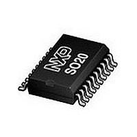
SAA6588T NXP Semiconductors, SAA6588T Datasheet - Page 19

SAA6588T
Manufacturer Part Number
SAA6588T
Description
Manufacturer
NXP Semiconductors
Datasheet
1.SAA6588T.pdf
(32 pages)
Specifications of SAA6588T
Operating Temperature (min)
-40C
Operating Temperature (max)
85C
Operating Temperature Classification
Industrial
Mounting
Surface Mount
Pin Count
20
Lead Free Status / Rohs Status
Compliant
Available stocks
Company
Part Number
Manufacturer
Quantity
Price
Company:
Part Number:
SAA6588T
Manufacturer:
PHILIPS
Quantity:
15
Company:
Part Number:
SAA6588T
Manufacturer:
NXPLIPS
Quantity:
2 865
Part Number:
SAA6588T
Manufacturer:
PHILIPS/飞利浦
Quantity:
20 000
Part Number:
SAA6588T/V2
Manufacturer:
PHILIPS/飞利浦
Quantity:
20 000
Philips Semiconductors
I
I
In communication with the pre-processor two basic types
of I
Every transmission begins with a START condition ‘S’
followed by the 7-bit slave address and the R/W mode bit,
all generated by the external master.
The 6 higher bits of the pre-processors slave address are
fixed to 001000. The least significant bit of the slave
address can be set via the external input pin MAD to
enable a variation if the slave address is already occupied
by another device of the radio set. Data is transferred with
the most significant bit (MSB) first.
Table 16 Transmitting to the pre-processor (write transfer)
Notes
1. S = START condition.
2. Slave address (depends on level at pin MAD) = 0010000 or 0010001.
3. W = write mode.
4. A = acknowledge bit (SDA = LOW).
5. Subsequently data bytes 0
6. P = STOP condition.
Table 17 Receiving from the pre-processor (read transfer)
Notes
1. S = START condition.
2. Slave address (depends on level at pin MAD) = 0010000 or 0010001.
3. R = read mode.
4. A = acknowledge bit (SDA = LOW). Six DATA-acknowledge sequences must occur before the DATA-not
5. Subsequently data bytes 0
6. A = no acknowledge (SDA = HIGH).
7. P = STOP condition.
2002 Jan 14
2
2
S
S
C-BUS PROTOCOL
C-bus format
(1)
(1)
RDS/RBDS pre-processor
2
acknowledge sequence.
C-bus protocols are allowed (see Tables 16 and 17).
SLAVE ADDRESS
SLAVE ADDRESS
(2)
(2)
W
R
, 1
to 6
W
R
W
(3)
R
(3)
and 2
.
W
A
A
(4)
.
(4)
DATA
DATA
(5)
(5)
19
Each transmitted byte is followed by an acknowledge bit
‘A’ (SDA = LOW). Every transmission is completed with a
STOP condition ‘P’ generated by the master.
During read or write transfer the master can abridge the
data transfer by generation of a STOP condition. In case
of transmission errors during a write cycle, the
pre-processor can indirectly stop the transfer by
generating no acknowledge (SDA = HIGH) hereafter the
master can send the STOP condition.
A
A
(4)
(4)
DATA
DATA
(5)
(5)
A
(4)
DATA
A
(6)
(5)
Product specification
SAA6588
A
(4)
P
(7)
P
(6)


