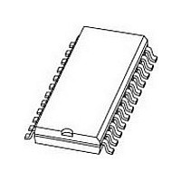
UBA2030T NXP Semiconductors, UBA2030T Datasheet - Page 15

UBA2030T
Manufacturer Part Number
UBA2030T
Description
Manufacturer
NXP Semiconductors
Datasheet
1.UBA2030T.pdf
(20 pages)
Specifications of UBA2030T
Number Of Drivers
4
Driver Type
High and Low Side
Frequency (max)
50KHz
Operating Supply Voltage (max)
570V
Peak Output Current
320mA
Operating Supply Voltage (min)
0V
Operating Temp Range
-40C to 150C
Operating Temperature Classification
Automotive
Mounting
Surface Mount
Pin Count
24
Package Type
SO
Lead Free Status / Rohs Status
Not Compliant
Available stocks
Company
Part Number
Manufacturer
Quantity
Price
Part Number:
UBA2030T
Manufacturer:
NXP/恩智浦
Quantity:
20 000
Company:
Part Number:
UBA2030T/N1
Manufacturer:
ZMD
Quantity:
1 064
Part Number:
UBA2030T/N1
Manufacturer:
PHILIPS/飞利浦
Quantity:
20 000
Part Number:
UBA2030T/N1/N
Manufacturer:
PHILIPS/飞利浦
Quantity:
20 000
Philips Semiconductors
Additional application information
The UBA2030T is the commutator part in a complete
system for driving an HID lamp. The life of the HID lamp
can depend on the amount of sodium that migrates
through its quartz wall. To minimize this migration, the
lamp must be operated negative with respect to system
ground.
Figure 7 shows a full bridge with an HID lamp in a typical
automotive configuration using a control unit referenced to
the high side of the bridge. Pin BER is connected to
system ground. The bridge can be held in its current state
by pin BE. The supply current to the internal low voltage
circuit is fed to pin HV which can be connected to either
system ground or to a low voltage DC supply, such as a
battery, as indicated by the dotted lines in Fig.7.
2002 Sep 27
handbook, full pagewidth
Full bridge driver IC
C1 = 150 nF.
C2 = 150 nF.
C3 = 220 nF.
C6 = 100 pF.
C
R
R
osc
osc
DT
low voltage
DC supply
= 50 to 1000 k (220 k results in a ‘dead time’ of 1 s).
= 10 nF.
= 147 k
high voltage
from
570 V (max)
system
ground
C i
C i
CONTROL
UNIT
C3
C6
R DT
C2
Fig.7 Automotive configuration (example 2).
SGND
GHR
SHR
EXO
V DD
FSR
DTC
HV
SD
13
14
15
18
20
21
22
23
24
UBA2030T
12
11
10
15
8
7
5
3
2
1
The diode in series with the supply to pin HV prevents C
being discharged if the lamp is shorted during the ignition
phase. C6 should be positioned as close as possible to
pin DTC. The control unit drives the MOSFETs relatively
hard which can cause radiation. To prevent switching the
MOSFETs hard, a resistor can be connected in series with
each gate.
In all applications, the voltage on pin HV must not be
allowed to become lower than the voltage at pin V
during the start-up phase or during normal operation,
otherwise the full bridge will not operate correctly. During
the start-up phase, pin EXO and pin SD should both be
LOW. The voltage as a function of time at pin EXO and
pin SD should be >5 V/ms.
SHL
GHL
FSL
BER
BE
RC
GLL
PGND
GLR
C osc
C1
R osc
HL
LL
C4
IGNITOR
LAMP
Product specification
C5
UBA2030T
MGL763
HR
LR
DD
i


