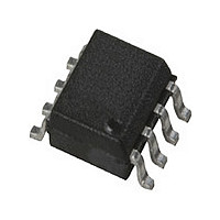
HMMC-3122-TR1 Avago Technologies US Inc., HMMC-3122-TR1 Datasheet - Page 5

HMMC-3122-TR1
Manufacturer Part Number
HMMC-3122-TR1
Description
Manufacturer
Avago Technologies US Inc.
Datasheet
1.HMMC-3122-TR1.pdf
(8 pages)
Specifications of HMMC-3122-TR1
Pin Count
8
Screening Level
Industrial
Package Type
SOIC
Lead Free Status / Rohs Status
Compliant
Assembly Notes
Independent of the bias applied to the package, the
backside of the package should always be connected
to both a good RF ground plane and a good thermal
heat sinking region on the PC–board to optimize
performance. For single–ended output operation the
unused RF output lead should be terminated into 50Ω
to a contact point at the V
through a dc blocking capacitor.
A minimum RF and thermal PC board contact area
equal to or greater than 2.67 x 1.65 mm (0.105" x
0.065") with eight 0.020" diameter plated–wall thermal
vias is recommended.
MMIC ESD precautions, handling considerations, die
attach and bonding methods are critical factors in
successful GaAs MMIC performance and reliability.
Figure 2. Package & Dimensions
Exposed heat sink on package bottom
must be soldered to PCB RF ground.
Figure 3. Assembly Diagram (Single-supply, Positive-bias Configuration shown)
5
V EE
CC
RFin
RFin
V CC
potential or to RF ground
V CC (+4 .5 to +6 .5 vo lts)
RFout
RFout
V CC
V CC
Avago Technologies application note #54, “GaAs MMIC
ESD, Die Attach and Bonding Guidelines” provides
basic information on these subjects.
Moisture Sensitivity Classification: Class 1, per JESD22-
A112-A.
Additional References:
PN
Notes:
-
-
-
-
All dimensions in millimeters.
Refer to JEDEC Outline MS-012 for additional tolerances.
Exposed heat slug area on pkg bottom = 2.67 x 1.65
Exposed heat sink on package bottom must be soldered to PCB
RF ground plane.
~ 1 mf Mon o b lo ck
#18,
To operate component from a negative supply, ground each
V CC connection and supply V EE with a negative voltage (-4.5
to -6.5v) bypassed to ground with ~ 1 m f capacitor.
RF out should be terminated in 50Ω to ground. (dc blocking
capacitor required for positive bias configuration.)
C apacito r
“HBT
Symbol
A
A1
B
C
D
E
e
H
L
a
Prescaler
Min
1.35
0.0
0.33
0.19
4.80
3.80
5.80
0.40
0°
Evaluation Board.”
1.27 BSC
Max
1.75
.25
0.51
.025
5.00
4.00
6.20
1.27
8°


