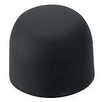
HE9Z-D5B IDEC, HE9Z-D5B Datasheet - Page 2

HE9Z-D5B
Manufacturer Part Number
HE9Z-D5B
Description
08N2438
Manufacturer
IDEC
Datasheet
1.HE9Z-D5B.pdf
(4 pages)
Specifications of HE9Z-D5B
Actuator / Cap Color
Black
For Use With
HE5B Series Pushbutton Enabling Switches
414
Part Numbers
Current Ratings
Circuit Diagrams
Terminal Arrangement (Bottom View)
Rated Insulation Voltage (Ui)
Thermal Current (lth)
Rated Operating Voltage (Ue)
Rated Operating
Current (le)
Contact Confi guration (3 Position Switch)
Rubber
Cover
With
NC1
NO1
NBR/PVC cover comes in gray only.
Minimum applicable load (reference): 3V AC/DC, 5mA.
1. 3 position switch: 2 contacts, terminal no. = between NO1-C1, between NO2-C2
2. Use between NO-C for OFF‡ On‡ OFF 3 position switch (NC is not used).
C1
Model
Silicone Rubber
NC2
NO2
C2
NBR/PVC
HE5B Series
AC
DC
Arrangement
Contact
DPDT
Resistive Load (AC-12)
Inductive Load (AC-15)
Resistive Load (DC-12)
Inductive Load (DC-13)
Yellow
Color
Black
Gray
Part Number
HE5B-M2PN1
HE5B-M2PY
HE5B-M2PB
0.7A
30V
1A
–
–
2 contacts (DPDT)
www.idec.com
125V
3A
Mounting Hole Layout
125V
0.5A
0.3A
–
–
Anti-rotation ring
Lock nut
1. Recommended tightening torque for Locking
2. Use a lock nut tool to screw on the lock nut
Ring: 0.29 to 0.49 N·mm.
(see page 415).
Enabling Switches


