CW1K-3AE11 IDEC, CW1K-3AE11 Datasheet - Page 19
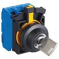
CW1K-3AE11
Manufacturer Part Number
CW1K-3AE11
Description
59T4337
Manufacturer
IDEC
Datasheet
1.CW1P-1EQ3R.pdf
(20 pages)
Specifications of CW1K-3AE11
Contact Configuration
1NO / 1NC
Switch Operation
On
Angle Of Throw
45°
Actuator Style
Key
No. Of Switch Positions
3
Contact Current Max
10A
Switch Terminals
Screw


Turn off the power to CW series switches before installation, removal,
wiring and maintenance. Failure to turn power off may cause electrical
shocks or fire hazard.
Operating Instructions
Notes for Operation
Operating Conditions
In corrosive gas or high-temperature, high-
humidity environments, contact failure due to
corrosion or color change or breakage of the
housing may occur.
Main parts of the CW series switches are
made of plastic. Do not scratch the surface
with a sharp object or apply excessive electric
shock or load, otherwise the switches may be
damaged. In particular, keep the button, lens
and bezel from such damage, otherwise ap-
pearance and function may be impaired.
Do not apply detergents, cutting oils, or
chemicals which may impair the function and
appearance of the CW series switches.
Panel Mounting
First remove the contact block and then the
locking ring from the operator. Insert the
operator into the panel cut-out from the front,
tighten the locking ring from the back, then
install the contact block to the operator.
Mounting Hole
1. Mounting hole dimensions are in compli-
2. If the anti-rotation projection is removed
Safety Precautions
When using the CW series switches in a
safety-related circuit of a control system,
observe safety rules and regulations of
each country concerning particular applica-
tions of the actual machines and facilities.
Perform risk assessment before operation
to ensure safety.
ance with IEC60947-5-1.
from the bezel, CW series switches can be
mounted in ø22.3mm mounting holes. To
remove the anti-rotation projection, remove
the gasket and use cutting pliers to break
the projection.
www.IDEC.com/switches
800.262.4332
Removing and Installing the Contact Unit
1. To remove the contact block from the opera-
2. To install, align the TOP marking on the
Installation in Panel Cut-out
Remove the locking ring from the operator.
With the anti-rotation projection on the opera-
tor aligned with the recess in the mounting
hole, insert the operator into the mounting
hole. Tighten the locking ring from the rear of
the panel.
Anti-rotation projection
Recess in mounting hole
Note for Panel Mounting
When installing the operator in a panel cut-
out, use the optional locking ring wrench
(MW9Z-T1) to tighten the locking ring to a
recommended tightening torque of 1.2 N·m. Do
not use pliers and do not tighten excessively,
otherwise the operator may be damaged.
tor, push the yellow locking lever and turn it
to the left.
operator with the TOP marking on the
contact block mounting adaptor, and turn
the locking lever to the right.
Locking Lever
TOP marking on selector and key
selector switches
When wiring, use wires of a proper size to meet the voltage and current
requirements. Tighten the M3.5 terminal screws to a tightening torque of
1.0 to 1.3 N·m. Failure to tighten the terminal screws may cause over-
heating and fire.
TOP marking on illuminated
pushbuttons, pushbuttons
and pilot lights
Locking Ring
Panel
Precautions & Instructions
Illuminated Pushbuttons and Pilot Lights
Removing the Lens
To remove the lens from an illuminated pushbutton
or pilot light, insert a flat screwdriver under the
flange of the lens at 90° from the TOP marking and
twist the screwdriver.
Do not insert the screwdriver too far and do not ap-
ply excessive force to the lens, otherwise the bezel
surface may be damaged.
Screwdriver Insertion Direction
Screwdriver Insertion Angle
Installing the Lens
Turn the groove in the lens to the TOP marking on
the operator housing. With the groove aligned with
the ridge, press the lens in.
Marking
Marking film can be applied for inscriptions or
identification. (Marking plates are not available for
CW series illuminated pushbuttons and pilot lights.)
Applicable Marking Film Size
Thickness: 0.2 mm maximum
Film material: Polyester (recommended)
Note: Film is not supplied and must be provided by the user.
Illuminated Pushbutton (Round Flush)
Pilot Light (Round Flush, Round Extended)
TOP Marking
13.8
TOP Marking
TOP Marking
Ridge
Groove in the Lens
Illuminated Pushbutton
(Round Extended)
12.6
19
Related parts for CW1K-3AE11
Image
Part Number
Description
Manufacturer
Datasheet
Request
R

Part Number:
Description:
59T4338
Manufacturer:
IDEC
Datasheet:
Part Number:
Description:
59T4339
Manufacturer:
IDEC
Datasheet:
Part Number:
Description:
59T4340
Manufacturer:
IDEC
Datasheet:
Part Number:
Description:
59T4336
Manufacturer:
IDEC
Datasheet:
Part Number:
Description:
59T4335
Manufacturer:
IDEC
Datasheet:

Part Number:
Description:
Cable; Between IDEC MicroSmart (port 1 or 2) and HG2F/3F/4F; 5 ft.
Manufacturer:
IDEC Corporation
Datasheet:
Part Number:
Description:
Cable; Between IDEC Micro^3C/ONC/MicroSmart (port 2) PLCs and HG2F/3F/4F; 5 ft.
Manufacturer:
IDEC Corporation
Datasheet:
Part Number:
Description:
Angled Key for Idec HS6B Safety Switch
Manufacturer:
IDEC Corporation
Datasheet:
Part Number:
Description:
Accessory, L-Shaped Key for Idec HS5B and HS5E Safety Switch
Manufacturer:
IDEC Corporation
Datasheet:
Part Number:
Description:
Accessory, Straight Key for Idec HS5B and HS5E Safety Switch
Manufacturer:
IDEC Corporation
Datasheet:
Part Number:
Description:
INDICATOR INCANDESCENT LAMP, GREEN
Manufacturer:
IDEC
Datasheet:

Part Number:
Description:
LAMP, INDICATOR, INCAND, AMB
Manufacturer:
IDEC
Datasheet:
Part Number:
Description:
LAMP, INDICATOR, INCAND, GRN
Manufacturer:
IDEC
Datasheet:
Part Number:
Description:
LAMP, INDICATOR, INCAND, GRN
Manufacturer:
IDEC
Datasheet:
Part Number:
Description:
LAMP, INDICATOR, INCANDESCENT, RED
Manufacturer:
IDEC
Datasheet: