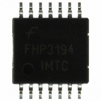
FHP3194IMTC14X Fairchild Semiconductor, FHP3194IMTC14X Datasheet - Page 4

FHP3194IMTC14X
Manufacturer Part Number
FHP3194IMTC14X
Description
MUX 4:1 ANALOG HI SPEED 14-TSSOP
Manufacturer
Fairchild Semiconductor
Datasheet
1.FHP3194IM14X.pdf
(17 pages)
Specifications of FHP3194IMTC14X
Function
Multiplexer
Circuit
1 x 4:1
Voltage Supply Source
Single Supply
Voltage - Supply, Single/dual (±)
5 V ~ 12 V
Operating Temperature
-40°C ~ 85°C
Mounting Type
Surface Mount
Package / Case
14-TSSOP
Lead Free Status / RoHS Status
Lead free / RoHS Compliant
Other names
FHP3194IMTC14XTR
© 2006 Fairchild Semiconductor Corporation
FHP3194 Rev. 1.0.1
Electrical Characteristics at ±5V
T
Notes:
1.
Frequency Domain Response
Time Domain Response
Distortion / Noise Response
DC Performance
Switching Characteristics
A
100% tested at 25°C
UGBW
BW
BW
t
t
OS
SR
HD2
HD3
THD
DG
DP
e
i
i
X
V
dV
V
I
dI
I
dI
GM
PSRR
I
I
I
T
V
Symbol
n+
n-
R
S
bn
bi
S
EN
SD
n
= 25°C, V
TALK
IO
IOM
S
SW
bn
bni
, t
IO
SS
LS
F
s
-3dB Bandwidth
-3dB Bandwidth
Full Power Bandwidth
0.1dB Gain Flatness
0.1dB Gain Flatness
Rise and Fall Time
Settling Time to 0.1%
Overshoot
Slew Rate
2nd Harmonic Distortion
3rd Harmonic Distortion
Total Harmonic Distortion
Differential Gain
Differential Phase
Input Voltage Noise
Input Current Noise (+)
Input Current Noise (-)
All Hostile Crosstalk
Input Offset Voltage
Input Offset Voltage Matching
Input Bias Current Non-inverting
Input Bias Current Inverting
Gain Matching
Power Supply Rejection Ratio
Supply Current
Disable Supply Current
Shutdown Supply Current
Switching Time 50% Logic to:
Channel Switch. Trans. (Glitch)
= ±5V, R
Average Drift
Average Drift
Average Drift
90% output (10% output
settling)
99% output (1% output
settling)
Parameter
f
= 475
(2)
(2)
(1)
Ω
, R
(1)
L
(1)
=150
(1)
(1)
(1)
(1)
(1)
Ω
, G = 2; unless otherwise noted.
G = +1, R
V
G = +2, V
G = +2, V
G = +2, V
G = +2, V
V
V
V
4V step
2V
2V
2V
NTSC (3.58MHz), DC-coupled
NTSC (3.58MHz), DC-coupled
> 1MHz
> 1MHz
> 1MHz
Channel-to-channel 5MHz/
30MHz, worst CH combination
Channel-to-channel
Pins 1,3,5,7
Pin 12
Channel-to-channel
DC
Disable mode
Shutdown mode
Channel-to-channel
IN1, IN3 = +0.5V;
IN2, IN4 = -0.5V
IN1, IN3 = +0.5V;
IN2, IN4 = -0.5V
All inputs grounded
OUT
OUT
OUT
OUT
pp
pp
pp
, 5MHz, worst channel
, 5MHz, worst channel
, 5MHz, worst channel
= 2V step; (10% to 90%)
= 0.2V
= 2V step
= 0.2V step
Conditions
OUT
OUT
OUT
OUT
f
4
= 1.5kΩ
pp
= 0.2V
= 2V
= 0.2V
= 2V
pp
pp
pp
pp
Min.
-30
-35
54
-9
-5
-68/-53
1200
2200
Typ.
0.02
0.05
0.02
800
500
200
375
-68
-89
-67
8.5
0.8
3.5
2.5
90
15
22
16
25
13
20
65
13
25
40
1
4
7
1
4
Max.
+9
30
35
18
5
6
5
www.fairchildsemi.com
nV/√Hz
Units
pA/Hz
pA/Hz
µV/°C
nA/°C
nA/°C
mV
MHz
MHz
MHz
MHz
MHz
V/µs
dBc
dBc
mV
V/°C
mV
mA
mA
mA
dB
dB
µA A
µA A
dB
ns
ns
ns
ns
%
%
%
°
/°C
/°C
pp


