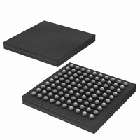
DS2155G Maxim Integrated Products, DS2155G Datasheet - Page 98

DS2155G
Manufacturer Part Number
DS2155G
Description
IC TXRX T1/E1/J1 1-CHIP 100CSBGA
Manufacturer
Maxim Integrated Products
Specifications of DS2155G
Function
Single-Chip Transceiver
Interface
E1, HDLC, J1, T1
Number Of Circuits
1
Voltage - Supply
3.14 V ~ 3.47 V
Current - Supply
75mA
Operating Temperature
0°C ~ 70°C
Mounting Type
Surface Mount
Package / Case
100-LFBGA
Includes
BERT Generator and Detector, CMI Coder and Decoder, HDLC Controller
Lead Free Status / RoHS Status
Contains lead / RoHS non-compliant
Power (watts)
-
Available stocks
Company
Part Number
Manufacturer
Quantity
Price
Part Number:
DS2155G+
Manufacturer:
MAXIM/ç¾ژن؟،
Quantity:
20 000
Company:
Part Number:
DS2155G+T&R
Manufacturer:
MAXIM
Quantity:
68
Company:
Part Number:
DS2155G+T&R
Manufacturer:
Maxim Integrated
Quantity:
10 000
Company:
Part Number:
DS2155G/T&R
Manufacturer:
Maxim Integrated
Quantity:
10 000
Part Number:
DS2155GN+
Manufacturer:
DALLAS
Quantity:
20 000
Company:
Part Number:
DS2155GNC2+T&R
Manufacturer:
MAXIM
Quantity:
14
Register Name:
Register Description:
Register Address:
Bit #
Name
Default
Bits 0 to 5/Channel Pointer Address Bits (IAA0 to IAA5). These bits select the channel to be programmed with
the idle code defined in the PCICR register. IAA0 is the LSB of the 5-bit channel code. Channel 1 is 01h.
Bit 6/Global Transmit-Idle Code (GTIC). Setting this bit causes all transmit channels to be set to the idle code
written to the PCICR register. This bit must be set = 0 for read operations. The value in bits IAA0–IAA5 must be a
valid transmit channel (01h to 20h for E1 mode; 01h to 18h for T1 mode).
Bit 7/Global Receive-Idle Code (GRIC). Setting this bit causes all receive channels to be set to the idle code
written to the PCICR register. This bit must be set = 0 for read operations. The value in bits IAA0–IAA5 must be a
valid transmit channel (01h to 20h for E1 mode; 01h to 18h for T1 mode).
Table 17-B. GRIC and GTIC Functions
Register Name:
Register Description:
Register Address:
Bit #
Name
Default
Bits 0 to 7/Per-Channel Idle-Code Bits (C0 to C7). This register defines the idle code to be programmed in the
channel selected by the IAAR register. C0 is the LSB of the idle code (this bit is transmitted last).
GRIC
0
0
1
1
GTIC
GRIC
0
1
0
1
C7
7
7
0
0
Updates a single transmit or receive channel
Updates all transmit channels
Updates all receive channels
Updates all transmit and receive channels
GTIC
C6
IAAR
Idle Array Address Register
7Eh
PCICR
Per-Channel Idle Code Register
7Fh
6
0
6
0
IAA5
C5
5
0
5
0
FUNCTION
IAA4
C4
4
0
4
0
98 of 238
IAA3
C3
3
0
3
0
IAA2
C2
2
0
2
0
IAA1
C1
1
0
1
0
IAA0
C0
0
0
0
0


