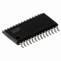
SC16IS752IPW,128 NXP Semiconductors, SC16IS752IPW,128 Datasheet - Page 28

SC16IS752IPW,128
Manufacturer Part Number
SC16IS752IPW,128
Description
IC DUAL UART 64BYTE 28TSSOP
Manufacturer
NXP Semiconductors
Datasheet
1.SC16IS752IBS151.pdf
(59 pages)
Specifications of SC16IS752IPW,128
Features
Low Current
Number Of Channels
2, DUART
Fifo's
64 Byte
Protocol
RS232, RS485
Voltage - Supply
2.5V, 3.3V
With Auto Flow Control
Yes
With Irda Encoder/decoder
Yes
With False Start Bit Detection
Yes
With Modem Control
Yes
Mounting Type
Surface Mount
Package / Case
28-TSSOP (0.173", 4.40mm Width)
For Use With
568-4000 - DEMO BOARD SPI/I2C TO DUAL UART568-3510 - DEMO BOARD SPI/I2C TO UART
Lead Free Status / RoHS Status
Lead free / RoHS Compliant
Other names
935279292128
SC16IS752IPW-F
SC16IS752IPW-F
SC16IS752IPW-F
SC16IS752IPW-F
NXP Semiconductors
SC16IS752_SC16IS762_7
Product data sheet
8.10 Scratchpad Register (SPR)
8.9 Modem Status Register (MSR)
This 8-bit register provides information about the current state of the control lines from the
modem, data set, or peripheral device to the host. It also indicates when a control input
from the modem changes state.
channel.
Table 21.
Remark: The primary inputs RI, CD, CTS, DSR are all active LOW.
The SC16IS752/SC16IS762 provides a temporary data register to store 8 bits of user
information.
Bit
7
6
5
4
3
2
1
0
Symbol
MSR[7]
MSR[6]
MSR[5]
MSR[4]
MSR[3]
MSR[2]
MSR[1]
MSR[0]
Modem Status Register bits description
Dual UART with I
Description
CD (active HIGH, logical 1). If GPIO6 or GPIO2 is selected as CD
modem pin through IOControl register bit 1 or bit 2, the state of CD pin
can be read from this bit. This bit is the complement of the CD input.
Reading IOState bit 6 or bit 2 does not reflect the true state of CD pin.
RI (active HIGH, logical 1). If GPIO7 or GPIO3 is selected as RI modem
pin through IOControl register bit 1 or bit 2, the state of RI pin can be
read from this bit. This bit is the complement of the RI input. Reading
IOState bit 7 or bit 3 does not reflect the true state of RI pin.
DSR (active HIGH, logical 1). If GPIO4 or GPIO0 is selected as DSR
modem pin through IOControl register bit 1 or bit 2, the state of DSR pin
can be read from this bit. This bit is the complement of the DSR input.
Reading IOState bit 4 or bit 0 does not reflect the true state of DSR pin.
CTS (active HIGH, logical 1). This bit is the complement of the CTS
input.
Cleared on a read.
Rev. 07 — 19 May 2008
CD. Indicates that CD input has changed state. Cleared on a read.
RI. Indicates that RI input has changed state from LOW to HIGH.
DSR. Indicates that DSR input has changed state. Cleared on a read.
CTS. Indicates that CTS input has changed state. Cleared on a read.
Table 21
2
shows Modem Status Register bit settings per
SC16IS752/SC16IS762
C-bus/SPI interface, 64-byte FIFOs, IrDA SIR
© NXP B.V. 2008. All rights reserved.
28 of 59


