NS16C2752TVA/NOPB National Semiconductor, NS16C2752TVA/NOPB Datasheet - Page 24
NS16C2752TVA/NOPB
Manufacturer Part Number
NS16C2752TVA/NOPB
Description
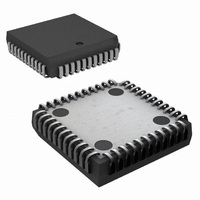
IC UART DUAL 64BYTE 44-PLCC
Manufacturer
National Semiconductor
Datasheet
1.NS16C2552TVSXNOPB.pdf
(44 pages)
Specifications of NS16C2752TVA/NOPB
Features
Programmable
Number Of Channels
2, DUART
Fifo's
64 Byte
Voltage - Supply
2.97 V ~ 5.5 V
With Auto Flow Control
Yes
With Irda Encoder/decoder
Yes
With Modem Control
Yes
Mounting Type
Surface Mount
Package / Case
44-LCC (J-Lead)
Lead Free Status / RoHS Status
Lead free / RoHS Compliant
Other names
NS16C2752TVA
Available stocks
Company
Part Number
Manufacturer
Quantity
Price
Company:

Part Number:
NS16C2752TVA/NOPB
Manufacturer:
Texas Instruments
Quantity:
10 000


www.national.com
6.12 ALTERNATE FUNCTION REGISTER (AFR)
This is a read/write register used to select simultaneous write
to both register sets and alter MF pin functions.
Bit
7:3
2:1
6.13 DEVICE IDENTIFICATION REGISTER (ID)
The device ID for NS16C2552 is 0x03. DLL and DLM should
be initialized to 0x00 before reading the ID register. This is a
read-only register.
0
Bit
7:4
3:0
Concurrent Write
MF Output Sel
Bit Name
Reserved
Default
Ena
Device Rev
Bit Name
Device ID
R/W
R/W
R/W
Def
0
0
TABLE 19. DREV (0x0, LCR[7]=1, LCR!=0xBF, DLL=DLM=0x00)
R/W
Def
R
R
Reserved
These bits are set to a logic 0.
Multi-function Pin Output Select
These select the output signal that will be present on the multi-function pin, MF. These bits are
individually programmable for each channel, so that different signals can be selected on each
channel.
Concurrent Write Enable
1 = CPU can write concurrently to the same register in both registers sets. This function is
intended to reduce the DUART initialization time. It can be used by a CPU when both channels
are initialized to the same state. The CPU can set or clear this bit by accessing either register
set. When this bit is set the channel select pin still selects the channel to be accessed during
read operations. Setting or clearing this bit has no effect on read operations.
The user should ensure that the DLAB bit LCR[7] of both channels are in the same state before
executing a concurrent write to register addresses 0, 1 and 2.
0 = No concurrent write (default). (No impact on read operations.)
TABLE 18. AFR (0x2, LCR[7] = 1, LCR != 0xBF)
AFR[2]
Device ID
Value = 0x3 for NS16C2552; 0x2 for NS16C2752
Device Revision
Value = 0x1.
1
1
0
0
AFR[1]
1
0
1
0
24
MF Function
= Reserved (MF output is forced logic 1)
= RXRDY
= BAUDOUT
= OUT2 (default)
Description
Description
Related parts for NS16C2752TVA/NOPB
Image
Part Number
Description
Manufacturer
Datasheet
Request
R

Part Number:
Description:
National Semiconductor [8-Bit D/A Converter]
Manufacturer:
National Semiconductor
Datasheet:
Part Number:
Description:
National Semiconductor [Media Coprocessor]
Manufacturer:
National Semiconductor
Datasheet:
Part Number:
Description:
Digitally Controlled Tone and Volume Circuit with Stereo Audio Power Amplifier, Microphone Preamp Stage and National 3D Sound
Manufacturer:
National Semiconductor
Datasheet:
Part Number:
Description:
Digitally Controlled Tone and Volume Circuit with Stereo Audio Power Amplifier, Microphone Preamp Stage and National 3D Sound
Manufacturer:
National Semiconductor
Datasheet:
Part Number:
Description:
AC97 Rev 2 Codec with Sample Rate Conversion and National 3D Sound
Manufacturer:
National Semiconductor
Part Number:
Description:
Manufacturer:
National Semiconductor
Datasheet:
Part Number:
Description:
Manufacturer:
National Semiconductor
Datasheet:
Part Number:
Description:
General Purpose, Low Voltage, Low Power, Rail-to-Rail Output Operational Amplifiers
Manufacturer:
National Semiconductor
Datasheet:
Part Number:
Description:
8-bit 20 MSPS flash A/D converter.
Manufacturer:
National Semiconductor
Datasheet:
Part Number:
Description:
Low Noise Quad Operational Amplifier
Manufacturer:
National Semiconductor
Datasheet:
Part Number:
Description:
Quad Differential Line Receivers
Manufacturer:
National Semiconductor
Datasheet:
Part Number:
Description:
Quad High Speed Trapezoidal? Bus Transceiver
Manufacturer:
National Semiconductor
Datasheet:
Part Number:
Description:
Dual Line Receiver
Manufacturer:
National Semiconductor
Datasheet:
Part Number:
Description:
TTL to 10k ECL Level Translator with Latch
Manufacturer:
National Semiconductor
Datasheet: