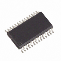
MAX3111EEWI+TG36 Maxim Integrated Products, MAX3111EEWI+TG36 Datasheet - Page 13

MAX3111EEWI+TG36
Manufacturer Part Number
MAX3111EEWI+TG36
Description
IC UART SPI COMPAT 28-SOIC
Manufacturer
Maxim Integrated Products
Datasheet
1.MAX3110ECWIG36.pdf
(31 pages)
Specifications of MAX3111EEWI+TG36
Features
Transceiver
Number Of Channels
1, UART
Protocol
RS232, RS485
Voltage - Supply
3 V ~ 3.6 V
With Irda Encoder/decoder
Yes
With False Start Bit Detection
Yes
With Cmos
Yes
Mounting Type
Surface Mount
Package / Case
28-SOIC (0.300", 7.50mm Width)
Lead Free Status / RoHS Status
Lead free / RoHS Compliant
Table 1. Bit Descriptions
Protected RS-232 Transceivers with Internal Capacitors
D0r–D7r
D0t–D7t
NAME
B0–B3
B0–B3
RAM
RAM
CTS
FEN
FEN
RTS
BIT
RM
RM
PM
PM
PE
PE
IR
IR
Pt
Pr
R
L
L
SPI/MICROWIRE-Compatible UART and ±15kV ESD-
TYPE
write
read
read
write
read
write
read
write
read
write
read
write
read
write
read
write
read
read
write
read
write
read
write
BIT
______________________________________________________________________________________
XXXXXXXX
00000000
change
STATE
POR
0000
0000
No
0
0
0
0
0
0
X
X
0
0
0
0
0
0
0
0
0
0
Baud-Rate Divisor Select Bits. Sets the baud clock’s value (Table 6).
Baud-Rate Divisor Select Bits. Reads the 4-bit baud clock value assigned to these registers.
Clear-to-Send-Input. Records the state of the CTS pin (CTS bit = 0 implies CTS pin = logic
high).
Transmit-Buffer Register. Eight data bits written into the transmit-buffer register. D7t is ignored
when L = 1.
Eight data bits read from the receive FIFO or the receive-buffer register. When L = 1, D7r is
always 0.
FIFO Enable. Enables the receive FIFO when FEN = 0. When FEN = 1, FIFO is disabled.
FIFO-Enable Readback. FEN’s state is read.
Enables the IrDA timing mode when IR = 1.
Reads the value of the IR bit.
Bit to set the word length of the transmitted or received data. L = 0 results in 8-bit words
(9-bit words if PE = 1) (see Figure 5). L = 1 results in 7-bit words (8-bit words if PE = 1).
Reads the value of the L bit.
Transmit-Parity Bit. This bit is treated as an extra bit that is transmitted if PE = 1. In 9-bit net-
works, the MAX3110E/MAX3111E do not calculate parity. If PE = 0, then this bit (Pt) is ignored
in transmit mode (see the 9-Bit Networks section).
Receive-Parity Bit. This bit is the extra bit received if PE = 1. Therefore, PE = 1 results in 9-bit
transmissions (L = 0). If PE = 0, then Pr is set to 0. Pr is stored in the FIFO with the receive data
(see the 9-Bit Networks section).
Parity-Enable Bit. Appends the Pt bit to the transmitted data when PE = 1, and sends the Pt bit
as written. No parity bit is transmitted when PE = 0. With PE = 1, an extra bit is expected to be
received. This data is put into the Pr register. Pr = 0 when PE = 0. The MAX3110E/MAX3111E
do not calculate parity.
Reads the value of the Parity-Enable bit.
Mask for Pr bit. IRQ is asserted if PM = 1 and Pr = 1 (Table 7).
Reads the value of the PM bit (Table 7).
Receive Bit or FIFO Not Empty Flag. R = 1 means new data is available to be read or is being
read from the receive register or FIFO. If performing a Read Data or Write Data operation, the R
bit will clear on the falling edge of SCLK's 16th pulse if no new data is available.
Mask for R bit. IRQ is asserted if RM = 1 and R = 1 (Table 7).
Reads the value of the RM bit (Table 7).
Mask for RA/FE bit. IRQ is asserted if RAM = 1 and RA/FE = 1 (Table 7).
Reads the value of the RAM bit (Table 7).
Request-to-Send Bit. Controls the state of the RTS output. This bit is reset on power-up (RTS
bit = 0 sets the RTS pin = logic high).
DESCRIPTION
13


