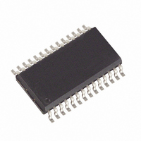
MAX3111EEWI+TG36 Maxim Integrated Products, MAX3111EEWI+TG36 Datasheet - Page 17

MAX3111EEWI+TG36
Manufacturer Part Number
MAX3111EEWI+TG36
Description
IC UART SPI COMPAT 28-SOIC
Manufacturer
Maxim Integrated Products
Datasheet
1.MAX3110ECWIG36.pdf
(31 pages)
Specifications of MAX3111EEWI+TG36
Features
Transceiver
Number Of Channels
1, UART
Protocol
RS232, RS485
Voltage - Supply
3 V ~ 3.6 V
With Irda Encoder/decoder
Yes
With False Start Bit Detection
Yes
With Cmos
Yes
Mounting Type
Surface Mount
Package / Case
28-SOIC (0.300", 7.50mm Width)
Lead Free Status / RoHS Status
Lead free / RoHS Compliant
Notes:
bit 15: DOUT
R = 1, Data is available to be read or is being read from the
receive register or FIFO.
R = 0, Receive register and FIFO are empty.
bit 14: DOUT
T = 1, Transmit buffer is empty.
T = 0, Transmit buffer is full.
bit 13: DOUT
FEN = 0, FIFO is enabled.
FEN = 1, FIFO is disabled.
bit 12: DOUT
SHDNo = 1, Software shutdown is enabled.
SHDNo = 0, Software shutdown is disabled.
bit 11: DOUT
TM = 1, Transmit buffer empty interrupt is enabled.
TM = 0, Transmit buffer empty interrupt is disabled.
bit 10: DOUT
RM = 1, Data available in the receive register or FIFO interrupt
is enabled.
RM = 0, Data available in the receive register or FIFO interrupt
is disabled.
bit 9: DOUT
PM = 1, Parity bit high received interrupt is enabled.
PM = 0, Parity bit received interrupt is disabled.
bit 8: DOUT
RAM = 1, Receiver-activity (shutdown mode)/Framing-error
(normal operation) interrupt is enabled.
RAM = 0, Receiver-activity (shutdown mode)/Framing-error
(normal operation) interrupt is disabled.
bit 7: DOUT
IR = 1, IrDA mode is enabled.
IR = 0, IrDA mode is disabled.
bit 6: DOUT
ST = 1, Transmit two stop-bits.
ST = 0, Transmit one stop-bit.
bit 5: DOUT
PE = 1, Parity is enabled for both transmit (state of Pt) and
receive.
PE = 0, Parity is disabled for both transmit and receive.
bit 4: DOUT
L = 1, 7-bit words (8-bit words if PE = 1)
L = 0, 8-bit words (9-bit words if PE = 1)
bits 3–0: DOUT
B3–B0 = XXXX Baud-Rate Divisor Select Bits (see Table 6)
Table 3. Read Configuration (D15, D14 = 0, 1)
D15 is present at DOUT on CS’s falling edge. Consecutive bits are clocked out on SCLK’s falling edge.
Protected RS-232 Transceivers with Internal Capacitors
DOUT
DIN
BIT
SPI/MICROWIRE-Compatible UART and ±15kV ESD-
15
R
0
14
1
T
______________________________________________________________________________________
FEN
13
0
SHDNo
12
0
TM
11
0
RM
10
0
PM
9
0
RAM
8
0
bit 15, 14: DIN
0,1 = Read Configuration
bits 13–1: DIN
Zeros
bit 0: DIN
If TEST = 1 and CS = 0, then RTS =16xBaudCLK
TEST = 0, Disables test mode
IR
7
0
ST
6
0
PE
5
0
4
0
L
B3
3
0
B2
2
0
B1
1
0
TEST
B0
0
17


