SC16C554IB80,557 NXP Semiconductors, SC16C554IB80,557 Datasheet - Page 11
SC16C554IB80,557
Manufacturer Part Number
SC16C554IB80,557
Description
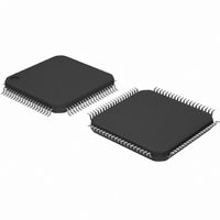
IC UART QUAD SOT315-1
Manufacturer
NXP Semiconductors
Datasheet
1.SC16C554DIA68512.pdf
(55 pages)
Specifications of SC16C554IB80,557
Number Of Channels
4, QUART
Fifo's
16 Byte
Voltage - Supply
2.5V, 3.3V, 5V
With Auto Flow Control
Yes
With Irda Encoder/decoder
Yes
With False Start Bit Detection
Yes
With Modem Control
Yes
With Cmos
Yes
Mounting Type
Surface Mount
Package / Case
80-LQFP
Lead Free Status / RoHS Status
Lead free / RoHS Compliant
Other names
935270075557
SC16C554IB80
SC16C554IB80
SC16C554IB80
SC16C554IB80


Philips Semiconductors
Table 2:
9397 750 13132
Product data
Symbol
IOW
IRQ
n.c.
RESET
(RESET)
RIA, RIB,
RIC, RID
RTSA, RTSB,
RTSC, RTSD
R/W
Pin description
Pin
PLCC68 LQFP64 LQFP80
18
15
21, 49,
52, 54,
55, 65
37
8, 28,
42, 62
14, 22,
48, 56
18
9
-
-
27
63, 19,
30, 50
5, 13,
36, 44
-
…continued
31
-
1, 10,
20, 21,
30, 40,
41, 49,
52, 60,
61, 71,
80
53
18, 43,
58, 3
26, 35,
66, 75
-
Quad UART with 16-byte FIFO and infrared (IrDA) encoder/decoder
Type
I
O
-
I
I
O
I
Rev. 05 — 10 May 2004
Description
Input/Output Write strobe (Active-LOW). This function is
associated with the 16 mode only. A logic 0 transition on this pin will
transfer the contents of the data bus (D0-D7) from the external CPU
to an internal register that is defined by address bits A0-A2. When
the 68 mode is selected, this pin functions as R/W (see definition
under R/W).
Interrupt Request or Interrupt ‘A’. This function is associated with
the 68 mode only. In the 68 mode, interrupts from UART channels
A-D are wire-ORed internally to function as a single IRQ interrupt.
This pin transitions to a logic 0 (if enabled by the interrupt enable
register) whenever a UART channel(s) requires service. Individual
channel interrupt status can be determined by addressing each
channel through its associated internal register, using CS and A3-A4.
In the 68 mode, and external pull-up resistor must be connected
between this pin and V
when operating in the 16 mode (see definition under INTA).
Not connected.
Reset. In the 16 mode, a logic 1 on this pin will reset the internal
registers and all the outputs. The UART transmitter output and the
receiver input will be disabled during reset time. (See
“SC16C554/554D external reset conditions”
When 16/68 is a logic 0 (68 mode), this pin functions similarly, but as
an inverted reset interface signal, RESET.
Ring Indicator (Active-LOW). These inputs are associated with
individual UART channels, A through D. A logic 0 on this pin indicates
the modem has received a ringing signal from the telephone line. A
logic 1 transition on this input pin will generate an interrupt.
Request to Send (Active-LOW). These outputs are associated with
individual UART channels, A through D. A logic 0 on the RTS pin
indicates the transmitter has data ready and waiting to send. Writing
a logic 1 in the modem control register MCR[1] will set this pin to a
logic 0, indicating data is available. After a reset this pin will be set to
a logic 1. This pin only affects the transmit and receive operations
when Auto RTS function is enabled via the Enhanced Feature
Register (EFR[6]) for hardware flow control operation.
Read/Write strobe. This function is associated with the 68 mode
only. This pin provides the combined functions for Read or Write
strobes.
Logic 1 = Read from UART register selected by CS and A0-A4.
Logic 0 = Write to UART register selected by CS and A0-A4.
CC
. The function of this pin changes to INTA
SC16C554/554D
© Koninklijke Philips Electronics N.V. 2004. All rights reserved.
for initialization details.)
Section 7.11
11 of 55
Related parts for SC16C554IB80,557
Image
Part Number
Description
Manufacturer
Datasheet
Request
R

Part Number:
Description:
NXP Semiconductors designed the LPC2420/2460 microcontroller around a 16-bit/32-bitARM7TDMI-S CPU core with real-time debug interfaces that include both JTAG andembedded trace
Manufacturer:
NXP Semiconductors
Datasheet:

Part Number:
Description:
NXP Semiconductors designed the LPC2458 microcontroller around a 16-bit/32-bitARM7TDMI-S CPU core with real-time debug interfaces that include both JTAG andembedded trace
Manufacturer:
NXP Semiconductors
Datasheet:
Part Number:
Description:
NXP Semiconductors designed the LPC2468 microcontroller around a 16-bit/32-bitARM7TDMI-S CPU core with real-time debug interfaces that include both JTAG andembedded trace
Manufacturer:
NXP Semiconductors
Datasheet:
Part Number:
Description:
NXP Semiconductors designed the LPC2470 microcontroller, powered by theARM7TDMI-S core, to be a highly integrated microcontroller for a wide range ofapplications that require advanced communications and high quality graphic displays
Manufacturer:
NXP Semiconductors
Datasheet:
Part Number:
Description:
NXP Semiconductors designed the LPC2478 microcontroller, powered by theARM7TDMI-S core, to be a highly integrated microcontroller for a wide range ofapplications that require advanced communications and high quality graphic displays
Manufacturer:
NXP Semiconductors
Datasheet:
Part Number:
Description:
The Philips Semiconductors XA (eXtended Architecture) family of 16-bit single-chip microcontrollers is powerful enough to easily handle the requirements of high performance embedded applications, yet inexpensive enough to compete in the market for hi
Manufacturer:
NXP Semiconductors
Datasheet:
Part Number:
Description:
The XA-S3 device is a member of Philips Semiconductors? XA(eXtended Architecture) family of high performance 16-bitsingle-chip microcontrollers
Manufacturer:
NXP Semiconductors
Datasheet:

Part Number:
Description:
The NXP BlueStreak LH75401/LH75411 family consists of two low-cost 16/32-bit System-on-Chip (SoC) devices
Manufacturer:
NXP Semiconductors
Datasheet:
Part Number:
Description:
The NXP LPC3130/3131 combine an 180 MHz ARM926EJ-S CPU core, high-speed USB2
Manufacturer:
NXP Semiconductors
Datasheet:
Part Number:
Description:
The NXP LPC3141 combine a 270 MHz ARM926EJ-S CPU core, High-speed USB 2
Manufacturer:
NXP Semiconductors
Part Number:
Description:
The NXP LPC3143 combine a 270 MHz ARM926EJ-S CPU core, High-speed USB 2
Manufacturer:
NXP Semiconductors

Part Number:
Description:
The NXP LPC3152 combines an 180 MHz ARM926EJ-S CPU core, High-speed USB 2
Manufacturer:
NXP Semiconductors
Part Number:
Description:
The NXP LPC3154 combines an 180 MHz ARM926EJ-S CPU core, High-speed USB 2
Manufacturer:
NXP Semiconductors

Part Number:
Description:
Standard level N-channel enhancement mode Field-Effect Transistor (FET) in a plastic package using NXP High-Performance Automotive (HPA) TrenchMOS technology
Manufacturer:
NXP Semiconductors
Datasheet: