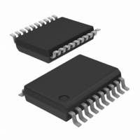
TDA8547TS/N1,112 NXP Semiconductors, TDA8547TS/N1,112 Datasheet - Page 5

TDA8547TS/N1,112
Manufacturer Part Number
TDA8547TS/N1,112
Description
IC AMP AUDIO PWR 1.2W AB 20SSOP
Manufacturer
NXP Semiconductors
Type
Class ABr
Datasheet
1.TDA8547TSN1118.pdf
(21 pages)
Specifications of TDA8547TS/N1,112
Output Type
2-Channel (Stereo)
Package / Case
20-SSOP
Max Output Power X Channels @ Load
1.2W x 2 @ 8 Ohm
Voltage - Supply
2.2 V ~ 18 V
Features
Depop, Mute, Short-Circuit and Thermal Protection, Standby
Mounting Type
Surface Mount
Product
Class-AB
Output Power
1.2 W
Available Set Gain
30 dB
Thd Plus Noise
0.15 %
Operating Supply Voltage
5 V
Maximum Power Dissipation
1100 mW
Maximum Operating Temperature
+ 85 C
Mounting Style
SMD/SMT
Audio Load Resistance
8 Ohms
Input Bias Current (max)
0.5 uA
Input Signal Type
Differential or Single
Minimum Operating Temperature
- 40 C
Output Signal Type
Differential, Single
Supply Type
Single
Supply Voltage (max)
18 V
Supply Voltage (min)
2.2 V
Lead Free Status / RoHS Status
Lead free / RoHS Compliant
Other names
935260066112
TDA8547TSDK
TDA8547TSDK
TDA8547TSDK
TDA8547TSDK
NXP Semiconductors
SELECT pin
If the voltage at the SELECT pin is in the range between
1.5 V and V
channels can be operational. If the SELECT pin is set to a
LOW voltage or grounded, then only channel 2 can
operate and the power amplifier of channel 1 will be in the
standby mode. In this case only the loudspeaker at
channel 2 can operate and the loudspeaker at channel 1
will be switched off. If the SELECT pin is set to a
HIGH level or connected to V
operate and the power amplifier of channel 2 will be in the
standby mode. In this case only the loudspeaker at
channel 1 can operate and the loudspeaker at channel 2
will be switched off. Setting the SELECT pin to a LOW or
Table 1 Control pins MODE and SELECT versus status of output channels
Voltage levels at control pins at V
Notes
1. HIGH = V
2. NC = not connected or floating.
3. X = don’t care.
4. HVP = 1.5 V < V
5. LOW = V
LIMITING VALUES
In accordance with the Absolute Maximum Rating System (IEC 134).
1998 Apr 01
V
V
I
T
T
V
P
SYMBOL
ORM
stg
amb
CC
I
Psc
tot
2 × 0.7 W BTL audio amplifier with
output channel switching
HVP
HVP
HVP
CC
HIGH
pin
supply voltage
input voltage
repetitive peak output current
storage temperature
operating ambient temperature
AC and DC short-circuit safe voltage
power dissipation
pin
− 1.5 V, or if it is kept floating, then both
LOW
MODE
HVP
(4)
(4)
(4)
< 0.5 V.
> V
(1)
/LOW
/LOW
/LOW
/NC
(4)
CC
(5)
pin
− 0.5 V.
(2)
< V
(5)
(5)
(5)
PARAMETER
CC
CC
CONTROL PIN
− 1.5 V.
, then only channel 1 can
P
= 5 V; for other supply voltages see Figs. 14 and 15.
HVP
HVP
HVP
SELECT
HIGH
LOW
operating
X
(4)
(4)
(4)
(3)
/NC
/NC
/NC
CONDITIONS
(5)
(1)
5
(2)
(2)
(2)
a HIGH voltage results in a reduction of quiescent current
consumption by a factor of approximately 2.
Switching with the SELECT pin during operating is not
plop-free, because the input capacitor of the channel
which is coming out of standby needs to be charged first.
For plop-free channel selecting the device has first to be
set in mute condition with the MODE pin (between 1.5 V
and V
level, after a delay set the MODE pin to a LOW level.
The delay needed depends on the values of the input
capacitor and the feedback resistors. Time needed is
approx. 10 × C1 × (R1 + R2), so approximately 0.6 s. for
the values in Fig.4.
CC
− 1.5 V), then set the SELECT pin to the new
CHANNEL 1 CHANNEL 2
−0.3
−0.3
−
−55
−40
−
−
mute/on
mute/on
STATUS OF OUTPUT
standby
standby
mute
MIN.
on
CHANNEL
+18
V
1
+150
+85
10
1.1
CC
mute/on
mute/on
standby
standby
MAX.
mute
+ 0.3
on
TDA8547TS
Product specification
V
V
A
°C
°C
V
W
TYP. I
(mA)
UNIT
15
15
15
8
8
0
q


