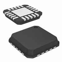
ISL54001IRTZ-T Intersil, ISL54001IRTZ-T Datasheet - Page 5

ISL54001IRTZ-T
Manufacturer Part Number
ISL54001IRTZ-T
Description
IC AMP AUDIO PWR 1.23W AB 20TQFN
Manufacturer
Intersil
Type
Class ABr
Datasheet
1.ISL54000IRTZ.pdf
(11 pages)
Specifications of ISL54001IRTZ-T
Output Type
2-Channel (Stereo)
Max Output Power X Channels @ Load
1.23W x 2 @ 8 Ohm
Voltage - Supply
2.7 V ~ 5.5 V
Features
Depop, Input Multiplexer, Shutdown, Thermal Protection
Mounting Type
Surface Mount
Package / Case
20-TQFN
Lead Free Status / RoHS Status
Lead free / RoHS Compliant
Electrical Specifications - 3.6V Supply
GENERAL
Quiescent Supply Current, I
Shutdown Supply Current, I
BTL AMPLIFIER DRIVER, HD = V
Output Offset Voltage, V
Power Supply Rejection Ratio, PSRR V
Output Power, P
Total Harmonic Distortion + Noise,
THD + N
Max Output Voltage Swing, V
LOGIC INPUT
Input Leakage Current, I
Electrical Specifications - 5V Supply
Crosstalk
R
Off-Isolation
Channel Gain Matching
R
Channel Phase Matching
R
LOGIC INPUT
Input Leakage Current, I
I
Input Leakage Current, I
I
V
V
MIX
MIX
CH
CH
CH
INH
INL
to L
to L
to L
CH
CH
CH
PARAMETER
PARAMETER
, L
CH
OUT
to R
SD
CH
OS
SD
SD
, I
INS
, I
, I
DD
SD
OUT
INS
INS
, I
MIX
,
,
5
INH,
R
from the input of active amplifier to the output of an
adjacent amplifier with its input AC coupled to ground.
SD = V
coupled from input to output of a disabled amplifier.
R
same source)
R
same source)
V
V
INS = 0V or V
AC coupled to ground (0.1µF)
INS = 0V or V
Input AC coupled to ground (0.1µF)
Measured between OUT_+ and OUT_-, Input AC
coupled to ground (0.1µF)
Input AC coupled to ground
(0.1µF)
R
R
R
R
R
V
DD
DD
L
L
L
RIPPLE
L
L
L
L
L
DD
HO = V
= 8Ω, VINxR = VINxL = 3.88V
= 8Ω, P
= 8Ω, VINxR = VINxL = 3.88V
= 8Ω, THD + N = 1%, f = 1kHz
= 8Ω, THD + N = 10%, f = 1kHz
= 8Ω, P
= 8Ω, P
= 8Ω, V
= 5V, SD = 0V, INS = 0V, MIX = 0V
= 5V, SD = V
= 5V, SD = 0V, INS = 0V, MIX = 0V
INH,
= 200mV
INH,
OUT
OUT
OUT
SIGNAL
P
ISL54000, ISL54001, ISL54002
OUT
DD
DD
UNLESS OTHERWISE SPECIFIED
Test Conditions: V
GS1 = V
Specified (Note 3).
TEST CONDITIONS
= 800mW, f = 1kHz, Signal coupled
Test Conditions: V
C
(Note 3). (Continued)
= 200mW, f = 1kHz
= 200mW, f = 20Hz to 20kHz
TEST CONDITIONS
, MIX = 0V or V
, MIX = 0V or V
REF
DD
= 800mW, f = 10kHz, Signal
P-P
= 3.6V
, INS = V
, R
= 1µF, R
INL
L
P-P
, C
= 8Ω,
, f = 1kHz
REF
DD
L
P-P
DD
P-P
DD
is terminated between OUT_+ and OUT_ -, Unless Otherwise Specified
, MIX = V
DD
= 1µF. R
F
F
, R
DD
, R
(Connect to the
RIPPLE
RIPPLE
(Connect to the
= +3.6V, GND = 0V, V
L
= +5V, GND = 0V, V
L
= None, Input
= 8Ω (BTL),
DD
L
= 217Hz
= 1kHz
is terminated between OUT_+ and OUT_ -, Unless Otherwise
TEMP
(°C)
Full
Full
Full
Full
25
25
25
25
25
25
TEMP
(°C)
Full
Full
Full
Full
25
25
25
25
25
25
25
25
25
25
25
INH
INH
= 2.4V, V
= 1.4V. V
(Notes 4, 5)
(Notes 4, 5)
MIN
2.4
-3
-1
-
-
-
-
-
-
-
MIN
-3
-
-
-
-
-
-
-
-
-
-
-
-
-
-
INL
INL
= 0.8V, SD = MIX = INS = V
= 0.4V, SD = MIX = INS = GSO =
+-0.1
TYP
0.01
0.02
0.02
130
1.9
1.9
80
-
-
TYP
310
528
2.7
0.4
0.4
5.8
1.9
1.9
13
15
25
40
49
47
3
(Notes 4, 5) UNITS
(Notes 4, 5) UNITS
MAX
0.8
-1
3
-
-
-
-
-
-
-
MAX
12
50
3
-
-
-
-
-
-
-
-
-
-
-
-
October 17, 2007
FN6458.2
INL
µA
µA
µA
µA
dB
dB
dB
V
V
°
V
mW
mW
mA
mV
mV
mA
µA
µA
dB
dB
µA
µA
%
%
P-P
,


