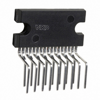
TDA8561Q/N3C,112 NXP Semiconductors, TDA8561Q/N3C,112 Datasheet - Page 14

TDA8561Q/N3C,112
Manufacturer Part Number
TDA8561Q/N3C,112
Description
IC AMP AUDIO PWR 24W STER 17SIL
Manufacturer
NXP Semiconductors
Type
Class Br
Datasheet
1.TDA8561QN3S112.pdf
(24 pages)
Specifications of TDA8561Q/N3C,112
Output Type
2-Channel (Stereo) or 4-Channel (Quad)
Package / Case
17-SIL (Bent and Staggered Leads)
Max Output Power X Channels @ Load
24W x 2 @ 4 Ohm; 12W x 4 @ 2 Ohm
Voltage - Supply
6 V ~ 18 V
Features
Depop, Differential Inputs, Mute, Short-Circuit and Thermal Protection, Standby
Mounting Type
Through Hole
Product
Class-B
Output Power
24 W
Available Set Gain
26 dB
Thd Plus Noise
0.06 %
Operating Supply Voltage
14.4 V
Maximum Power Dissipation
60000 mW
Maximum Operating Temperature
+ 85 C
Mounting Style
Through Hole
Audio Load Resistance
4 Ohms
Input Signal Type
Single
Minimum Operating Temperature
- 40 C
Output Signal Type
Differential, Single
Supply Type
Single
Supply Voltage (max)
18 V
Supply Voltage (min)
6 V
Lead Free Status / RoHS Status
Lead free / RoHS Compliant
Other names
935284509112
TDA8561Q/N3C
TDA8561Q/N3C
TDA8561Q/N3C
TDA8561Q/N3C
Philips Semiconductors
Mode select switch
To avoid switch-on plops, it is advised to keep the amplifier
in the mute mode during >100 ms (charging of the input
capacitors at pins 1, 3, 15 and 17.
The circuit in Fig.11 slowly ramps up the voltage at the
mode select switch pin when switching on and results in
fast muting when switching off.
1999 Jun 30
2
car radio power amplifier
(1) f = 10 kHz.
(2) f = 1 kHz.
(3) f = 100 Hz.
THD
10
10
(%)
10
10
24 W BTL or 4
1
10
1
2
2
2
Fig.12 Total harmonic distortion as a function of output power; V
10
12 W single-ended
1
14
1
handbook, halfpage
(1)
(2)
(3)
Fig.11 Mode select switch circuitry.
V P
47 F
10 k
P
= 14.4 V, R
10
L
100
100 k
P (W)
= 4
o
Product specification
TDA8561Q
MGA708
switch
select
mode
MGA709
10
2


