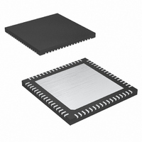
MAX2078CTK+ Maxim Integrated Products, MAX2078CTK+ Datasheet - Page 18

MAX2078CTK+
Manufacturer Part Number
MAX2078CTK+
Description
IC FRNT-END ULTRASOUND 8CH 68QFN
Manufacturer
Maxim Integrated Products
Type
Ultrasound Receiversr
Datasheet
1.MAX2078CTK.pdf
(26 pages)
Specifications of MAX2078CTK+
Applications
Medical Ultrasound Imaging, Sonar
Mounting Type
Surface Mount
Package / Case
68-TQFN Exposed Pad
Operating Supply Voltage
3.13 V to 3.47 V
Maximum Operating Temperature
+ 70 C
Mounting Style
SMD/SMT
Minimum Operating Temperature
0 C
Lead Free Status / RoHS Status
Lead free / RoHS Compliant
Octal-Channel Ultrasound Front-End
with CW Doppler Mixers
Each mixer can be programmed to 1 of 16 phases;
therefore, 4 bits are required for each channel for pro-
gramming. Each CW channel can be programmed to
an off state by setting bit Di to 1. The power-down
mode (PD) line overrides this soft shutdown.
After the serial shift registers have been programmed,
the CS signal, when going high, loads the phase infor-
mation in the form of 5 bits per channel into the I/Q
phase divider/selectors. This presets the dividers,
selecting the appropriate mixer phasing. See Table 3
for mixer phase configurations.
The outputs from the octal-channel mixer array are
summed internally to produce the total CWD summed
beamformed signal. The octal array produces eight
Table 3. Mixer Phase Configurations
Figure 1. Data Flow of Serial Shift Register
18
______________________________________________________________________________________
PHASE (DEGREE)
PER CHANNEL
112.5
157.5
202.5
247.5
292.5
337.5
22.5
67.5
135
180
225
270
315
45
90
0
CW Mixer Output Summation
B4
B4
A B C D SD
A B C D SD
CHANNEL 1
CHANNEL 5
B3 B2 B1 B0
B3 B2 B1 B0
Di + 4
MSB
0
1
0
1
0
1
0
1
0
1
0
1
0
1
0
1
B4
B4
A B C D SD
A B C D SD
CHANNEL 2
CHANNEL 6
B3 B2 B1 B0
B3 B2 B1 B0
Di + 3
CLK
DIN
0
0
1
1
0
0
1
1
0
0
1
1
0
0
1
1
differential quadrature (Q) outputs and eight differential
in-phase (I) outputs. All quadrature and in-phase out-
puts are summed into single I and Q differential current
outputs (CQ+, CQ-, CI+, CI-).
The LO phase dividers can be programmed through
the shift registers to allow for 16 quadrature phases for
a complete CW beamforming solution.
Figure 1 illustrates the serial programming of the eight
individual channels through the serial data port. Note
that the serial data can be daisy-chained from one part
to another, allowing a single data line to be used to pro-
gram multiple chips in the system.
B4
B4
D46
A B C D SD
A B C D SD
CHANNEL 3
CHANNEL 7
B3 B2 B1 B0
B3 B2 B1 B0
Di + 2
D45
0
0
0
0
1
1
1
1
0
0
0
0
1
1
1
1
D44
D43
B4
B4
A B C D SD
A B C D SD
D42
CHANNEL 4
CHANNEL 8
B3 B2 B1 B0
B3 B2 B1 B0
Di + 1
LSB
D41
0
0
0
0
0
0
0
0
1
1
1
1
1
1
1
1
D40
DOUT
LO Phase Select
Synchronization
SHUTDOWN
0/1
0/1
0/1
0/1
0/1
0/1
0/1
0/1
0/1
0/1
0/1
0/1
0/1
0/1
0/1
0/1
Di


