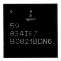
ISL59834IRZ Intersil, ISL59834IRZ Datasheet - Page 5

ISL59834IRZ
Manufacturer Part Number
ISL59834IRZ
Description
IC VIDEO FILTER CHRG PUMP 44-QFN
Manufacturer
Intersil
Datasheet
1.ISL59834IRZ.pdf
(17 pages)
Specifications of ISL59834IRZ
Applications
Filter
Number Of Circuits
4
-3db Bandwidth
9MHz
Current - Supply
28mA
Current - Output / Channel
50mA
Voltage - Supply, Single/dual (±)
3 V ~ 3.6 V
Mounting Type
Surface Mount
Package / Case
44-VQFN
Lead Free Status / RoHS Status
Lead free / RoHS Compliant
Pin Descriptions
12, 13, 16, 17, 18,
21, 35, 38, 40, 43
NUMBER
1, 3, 9, 11
6, 41
10
14
15
19
20
22
23
24
25
26
27
28
29
30
31
32
33
34
36
37
39
42
44
2
4
5
7
8
-
SYNC_OUTB
SYNC_OUTA
SYNC_INB
SYNC_INA
ENABLE
ENABLE
VEEB
VEEA
GND
GND
VEEB
VEEA
CAPB+
CAPA+
NAME
CAPB-
CAPA-
OUT4
OUT3
OUT2
OUT1
CLK
CLK
GND
V
V
IN2
IN3
IN4
NC
IN1
EP
V
CPA
CPB
S
CPB
CPA
5
OUT
OUT
B
A
IN
IN
B
A
Ground
Video Input 2. Chroma Channel.
Charge Pump A Ground
Charge Pump A Power Supply. Bypass with a 0.1µF capacitor to GND
Positive Power Supply. Bypass to GND with a 0.1µF capacitor.
Channel 3 and Channel 4 Enable. Connect to V
ENABLE
Video Input 3. Luma Channel.
Video Input 4. Chroma Channel.
No Connect.
Charge Pump B Ground.
Charge Pump B Power Supply. Bypass with a 0.1µF capacitor to GND
Charge-Pump B Flying Capacitor Negative Terminal. Connect a 0.1µF capacitor from CAPB+ to
CAPB-.
Charge-Pump B Flying Capacitor Positive Terminal. Connect a 0.1µF capacitor from CAPB+ to CAPB-
.
Charge Pump Negative Output. Bypass with a 0.22µF capacitor to GCP2.
Negative Supply for Channels 3 and 4. Connect an RC filter between VEEB
Typical Application Diagram. VEEA
Video Output 4
Video Output 3
Sync Input. Sync logic input for Channel 4.
Sync Output. Sync logic output from Channel 3.
Channel 3 and Channel 4 Charge Pump Clock Output. Can also be driven by external clock. CLK
must be tied to CLK
Charge-Pump A Flying Capacitor Negative Terminal. Connect a 0.1µF capacitor from CAPA+ to
CAPA-.
Charge-Pump A Flying Capacitor Positive Terminal. Connect a 0.1µF capacitor from CAPB+ to
CAPB-.
Charge Pump Negative Output. Bypass with a 0.22µF capacitor to GND
Negative Supply for Channels 1 and 2. Connect an RC filter between VEEA
Typical Application Diagram. VEEA
Video Output 2
Video Output 1
Sync Input. Sync logic input for Channel 2.
Sync Output. Sync logic output from Channel 1.
Channel 1 and Channel 2 Charge Pump Clock Output. Can also be driven by external clock. CLK
must be tied to CLK
Channel 1 and Channel 2 enable. Connect to V
ENABLE
Video Input 1. Luma Channel.
Exposed Pad. Connect to VEEA
B
B
.
.
ISL59834
B.
B.
IN
or VEEB
IN
IN
must be tied to VEEB
must be tied to VEEB
IN
FUNCTION
.
S
S
to enable channels. ENABLE
to enable channels. ENABLE
IN.
IN.
CPA.
CPB
CPA
.
.
IN
IN
and VEEB
and VEEA
A
A
must be tied to
must be tied to
OUT
OUT
June 11, 2008
. See
. See
FN6268.1
A
A


