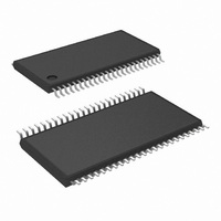
LM8207MTX/NOPB National Semiconductor, LM8207MTX/NOPB Datasheet - Page 17

LM8207MTX/NOPB
Manufacturer Part Number
LM8207MTX/NOPB
Description
IC BUFFER/DVR/VREF 48-TSSOP
Manufacturer
National Semiconductor
Datasheet
1.LM8207MTNOPB.pdf
(22 pages)
Specifications of LM8207MTX/NOPB
Applications
TFT-LCD Panels: Gamma Buffer, VCOM Driver
Output Type
Rail-to-Rail
Number Of Circuits
18
-3db Bandwidth
2MHz
Slew Rate
1 V/µs
Current - Supply
6.5mA
Current - Output / Channel
50mA
Voltage - Supply, Single/dual (±)
6 V ~ 16 V
Mounting Type
Surface Mount
Package / Case
48-TFSOP (0.240", 6.10mm Width)
Lead Free Status / RoHS Status
Lead free / RoHS Compliant
Other names
LM8207MTX
Application Section
V
The V
plate of all the pixels in a TFT panel. When column drivers
write to the pixels, current pulses will occur onto the V
line. These pulses are the result of charging the capacitance
between V
combination of stray capacitance and pixel capacitance. This
stray capacitance varies between panel sizes but typically
ranges from 16 pF to 33 pF per column. Pixel capacitance is
in the order of 0.5 pF and contributes very little to these
pulses because only one pixel at a time is connected to a
column. Charging this capacitance can result in short posi-
tive or negative current pulses of 100 mA or more, depend-
ing on the panel size. The V
these pulses. A V
that can sink or source current in large capacitive loads. The
V
bances. The operating voltage of the V
middle of the gamma voltage range.
COM
COM
BUFFER
COM
buffer should recover very fast from these distur-
COM
buffer supplies a common voltage to the back
and the column lines. This capacitance is a
FIGURE 11. VCOM Buffer
COM
buffer is basically a voltage regulator
COM
buffer is designed to handle
(Continued)
COM
buffer is in the
20137928
COM
17
The typical application in Figure 11 shows the V
supplying a common voltage to the back plate of the display.
This level can be adjusted by changing the value of the
resistors. Increasing the value of R
of R
R
level.
Another, more flexible, solution is to use National Semicon-
ductor’s programmable V
V
LM8342’s datasheet for more detailed information about this
part.
LM8207 CONFIGURATION
A complete configured typical application of the LM8207 is
given in Figure 12. All three basic functions of the LM8207
are discussed in the previous sections. Details for setting the
Voltage Reference are given in the “Voltage Reference”
section. Calculations for defining a gamma correction curve
are given in the section entitled “Gamma Buffers.” Defining
and adjusting the V
Buffer” section. The LM8207 is an 18 channel gamma buffer
plus a V
gamma buffers or the V
cases it is recommended that the unused buffer input pins be
tied to the input voltage range value.
COM
2
or decreasing the value of R
2
will decrease the V
level can be adjusted using an I
COM
buffer. In certain applications some of the
COM
COM
COM
COM
level is discussed in the “V
buffer may not be used. In such
level. Increasing the value of
calibrator, the LM8342. The
1
1
will increase the V
or decreasing the value
2
C interface. See the
www.national.com
COM
buffer
COM
COM


