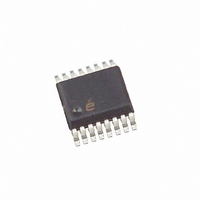
ISL59440IAZ-T13 Intersil, ISL59440IAZ-T13 Datasheet - Page 8

ISL59440IAZ-T13
Manufacturer Part Number
ISL59440IAZ-T13
Description
IC AMP MULTIPLEX 400MHZ 16-QSOP
Manufacturer
Intersil
Datasheet
1.ISL59440IAZ.pdf
(12 pages)
Specifications of ISL59440IAZ-T13
Applications
4:1 Multiplexer-Amplifier
Number Of Circuits
1
-3db Bandwidth
400MHz
Slew Rate
1470 V/µs
Current - Supply
14.5mA
Current - Output / Channel
130mA
Mounting Type
Surface Mount
Package / Case
16-QSOP
Lead Free Status / RoHS Status
Lead free / RoHS Compliant
AC Test Circuits
NOTE: Figure 24A illustrates the optimum output load when connecting to input terminated equipment. Figure 24B illustrates
backloaded test circuit for video cable applications.
Pin Descriptions
FIGURE 24A. TEST CIRCUIT FOR MEASURING WITH A 50Ω OR
PIN NUMBER
V
IN
50Ω
75Ω
OR
1, 3, 7
10
12
13
14
15
16
R
11
2
4
5
6
8
9
G
ISL59440
R
75Ω INPUT TERMINATED EQUIPMENT
F
C
L
PIN NAME
IN
ENABLE
GND
OUT
NIC
HIZ
IN0
IN1
IN2
IN3
A
IN-
S0
S1
V+
V-
V
462.5Ω
= 1, 2
475Ω
OR
R
S
EQUIVALENT
CIRCUIT 1.
CIRCUIT 3.
8
CIRCUIT
Circuit 1
Circuit 1
Circuit 4
Circuit 1
Circuit 1
Circuit 2
Circuit 2
Circuit 4
Circuit 4
Circuit 3
Circuit 1
Circuit 2
Circuit 2
50Ω
75Ω
OR
OUT
V+
V-
Not Internally Connected; it is recommended this pin be tied to ground to minimize crosstalk.
Input for Channel 0
Input for Channel 1
Ground pin
Input for Channel 2
Input for Channel 3
Channel selection pin LSB (binary logic code)
Channel selection pin MSB (binary logic code)
Negative power supply
Positive power supply
Output
Inverting input of output amplifier
Output disable (active high); there are internal pull-down resistors, so the device will be active with
no connection; “HI” puts the output in high impedance state.
Device enable (active low); there are internal pull-down resistors, so the device will be active with
no connection; "HI" puts device into power-down mode.
V+
V-
EQUIPMENT
50Ω
75Ω
OR
TEST
ISL59440
FIGURE 24B. BACKLOADED TEST CIRCUIT FOR VIDEO
V
IN
50Ω
75Ω
OR
LOGIC PIN
R
G
DESCRIPTION
ISL59440
R
GND
CABLE APPLICATION. BANDWIDTH AND
LINEARITY FOR R
DEGRADED.
F
V+
V-
A
C
V
L
= 1, 2
50Ω OR 75Ω
21k
33k
R
CIRCUIT 2.
S
CIRCUIT 4.
1.2V
+
L
-
LESS THAN 500Ω WILL BE
CAPACITIVELY
COUPLED
ESD CLAMP
GND.
V+
V-
EQUIPMENT
50Ω
OR
75Ω
October 10, 2007
TEST
FN6162.2


