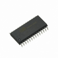
CS8420-DSZ Cirrus Logic Inc, CS8420-DSZ Datasheet - Page 4

CS8420-DSZ
Manufacturer Part Number
CS8420-DSZ
Description
IC CONV S/R DGTL AUDIO 28-SOIC
Manufacturer
Cirrus Logic Inc
Type
Sample Rate Converterr
Datasheet
1.CS8420-CSZ.pdf
(94 pages)
Specifications of CS8420-DSZ
Applications
Digital Audio
Mounting Type
Surface Mount
Package / Case
28-SOIC
Audio Control Type
Sample Rate Converter
Control Interface
3 Wire, Serial
Supply Voltage Range
4.75V To 5.25V
Operating Temperature Range
-40°C To +85°C
Audio Ic Case Style
SOIC
No. Of Pins
28
Lead Free Status / RoHS Status
Lead free / RoHS Compliant
Other names
598-1729
Available stocks
Company
Part Number
Manufacturer
Quantity
Price
Part Number:
CS8420-DSZ
Manufacturer:
CIRRUS
Quantity:
20 000
4
LIST OF FIGURES
16. PLL FILTER ........................................................................................................................................ 87
17. PARAMETER DEFINITIONS .............................................................................................................. 91
18. PACKAGE DIMENSIONS .................................................................................................................. 92
19. ORDERING INFORMATION .............................................................................................................. 93
20. REVISION HISTORY .......................................................................................................................... 93
Figure 1.Audio Port Master Mode Timing ................................................................................................... 9
Figure 2.Audio Port Slave Mode and Data Input Timing ............................................................................. 9
Figure 3.SPI Mode Timing ........................................................................................................................ 10
Figure 4.I²C Mode Timing ......................................................................................................................... 11
Figure 5.Recommended Connection Diagram for Software Mode ........................................................... 12
Figure 6.Software Mode Audio Data Flow Switching Options ................................................................... 14
Figure 7.CS8420 Clock Routing ................................................................................................................ 14
Figure 8.Serial Audio Input, using PLL, SRC Enabled .............................................................................. 16
Figure 9.Serial Audio Input, No PLL, SRC Enabled .................................................................................. 16
Figure 10.AES3 Input, SRC Enabled ........................................................................................................ 16
Figure 11.Serial Audio Input, AES3 Input Clock Source, SRC Enabled ................................................... 16
Figure 12.Serial Audio Input, SRC Output Clocked by AES3 Recovered Clock ....................................... 16
Figure 13.AES3 Input, SRC to Serial Audio Output, Serial Audio Input to AES3 Out ............................... 16
Figure 14.AES3 Input to Serial Audio Output, Serial Audio Input to AES3 Out, No SRC ......................... 17
Figure 15.AES3 Input to Serial Audio Output Only ................................................................................... 17
Figure 16.Input Serial Port to AES3 Transmitter ....................................................................................... 17
Figure 17.Serial Audio Input Example Formats ........................................................................................ 20
Figure 18.Serial Audio Output Example Formats ...................................................................................... 21
Figure 19.AES3 Receiver Timing for C & U Pin Output Data ................................................................... 23
Figure 20.AES3 Transmitter Timing for C, U and V Pin Input Data .......................................................... 26
Figure 21.Mono Mode Operation Compared to Normal Stereo Operation ............................................... 27
Figure 22.Control Port Timing in SPI Mode .............................................................................................. 30
Figure 23.Control Port Timing in I²C Mode ............................................................................................... 31
Figure 24.Hardware Mode 1 - Default Data Flow, AES3 Input ................................................................. 56
Figure 25.Hardware Mode 2 - Default Data Flow, Serial Audio Input ....................................................... 59
Figure 26.Hardware Mode 3 - Transceive Data Flow, with SRC .............................................................. 63
Figure 27.Hardware Mode 4 - Transceive Data Flow, Without SRC ......................................................... 67
Figure 28.Hardware Mode 5 - AES3 Receiver Only ................................................................................. 71
Figure 29.Hardware Mode 6 - AES3 Transmitter Only ............................................................................. 74
Figure 30.Professional Output Circuit ....................................................................................................... 78
Figure 31.Consumer Output Circuit .......................................................................................................... 78
Figure 32.TTL/CMOS Output Circuit ......................................................................................................... 79
Figure 33.Professional Input Circuit .......................................................................................................... 79
Figure 34.Transformerless Professional Input Circuit ............................................................................... 79
16.1 General ........................................................................................................................................ 87
16.2 External Filter Components ......................................................................................................... 87
16.3 Component Value Selection ........................................................................................................ 88
THERMAL CHARACTERISTICS AND SPECIFICATIONS ................................................................. 92
16.2.1 General ................................................................................................................................ 87
16.2.2 Capacitor Selection ............................................................................................................. 88
16.2.3 Circuit Board Layout ............................................................................................................ 88
16.3.1 Identifying the Part Revision ................................................................................................ 88
16.3.2 Locking to the RXP/RXN Receiver Inputs ........................................................................... 89
16.3.3 Locking to the ILRCK Input ................................................................................................. 89
16.3.4 Jitter Tolerance .................................................................................................................... 90
16.3.5 Jitter Attenuation ................................................................................................................. 90
CS8420
DS245F4


