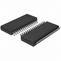
BH3854AFS-E2 Rohm Semiconductor, BH3854AFS-E2 Datasheet - Page 14

BH3854AFS-E2
Manufacturer Part Number
BH3854AFS-E2
Description
IC SERIAL SOUND CTRL SSOP-A32 TR
Manufacturer
Rohm Semiconductor
Type
Audio Processorr
Datasheet
1.BH3854AFS-E2.pdf
(16 pages)
Specifications of BH3854AFS-E2
Applications
Automotive
Mounting Type
Surface Mount
Package / Case
32-SSOP
Lead Free Status / RoHS Status
Lead free / RoHS Compliant
(7)
High-frequency digital signals are input into the CK,
DATA, and LATCH pins. Configure the wiring for these
pins in such a manner that it does not create interference
for lines carrying analog signals. When measuring for
step switching noise caused by interference, connect in
serial format resistance of approximately 2 k right next
to the microcomputer output pin (CK, DATA, LATCH) for
each line.
(8)
In the circuit of the sample application, a constant is giv-
en, as an example, to each of the VC (pin 23), TC (pin
22), BC (pin 21), and SC (pin 11) pins. These constants
vary depending upon signal level settings, wiring pat-
terns in the device to which they are mounted, etc. Con-
sider each constant carefully. The following diagram de-
picts an internal equivalent circuit. (It is equipped with a
primary integration circuit so that changes will occur
slowly.)
(9)
These specifications include, as reference values, fig-
ures for attenuation or gain for control serial data. The in-
ternal D / A converter features an R-2R structure, thus
when there is no change between consecutive data, data
exists. This can be used when very fine settings must be
made, provided that volume is 8 bits (256 steps) or fewer,
and tone is 5 bits (32 steps) or fewer.
646
Audio ICs
Serial control
Step switching noise
Setting the volume and tone levels
(10) D / A separation
With this IC (BH3854AS / AFS), the analog and digital
systems are completely separated in the power supply
and GND. Within the digital system, there is a stable built-
in standard voltage supply, all of which is supplied via the
VREF (pin 17, 3.8V), so this IC can be used without any
worry about timing being off or digital noise interference
occurring.
(11) Output pins
PORT 1 through 4 (pins 12 through 15) are reset when
the power is turned ON, and remain reset until the next
serial data is input.
Note: From the time the power is turned ON until the next
S Be sure that no more than 9V is applied to any of the
(12) Matrix surround
output pins.
The structure of the matrix surround is as shown in the
figure above. Use the equations shown in the figure to
calculate gain.
data is input, data in the CK, DATA, and LATCH
lines are all maintained at LOW.
BH3854AS / BH3854AFS


