BA3884F-E2 Rohm Semiconductor, BA3884F-E2 Datasheet - Page 5
BA3884F-E2
Manufacturer Part Number
BA3884F-E2
Description
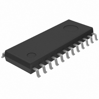
IC PROC HI DEFINITION SOP24 TR
Manufacturer
Rohm Semiconductor
Type
Audio Processorr
Datasheet
1.BA3884F-E2.pdf
(10 pages)
Specifications of BA3884F-E2
Applications
Automotive Systems, Players, TV
Mounting Type
Surface Mount
Package / Case
24-SOP
Lead Free Status / RoHS Status
Lead free / RoHS Compliant
Available stocks
Company
Part Number
Manufacturer
Quantity
Price
Company:

Part Number:
BA3884F-E2
Manufacturer:
SUMIDA
Quantity:
9 714
Part Number:
BA3884F-E2
Manufacturer:
ROHM/罗姆
Quantity:
20 000


Amplitude compensation (harmonic compensation)
To maintain appropriate auditory balance for the treble
region that is made up of harmonic components, a high-
speed detector and high-performance VCA circuit are
used for amplitude control of the treble component. The
amount of compensation is determined from a calcula-
tion performed based on the DC level input to the CTL1
pin, and the DC level detected from the input signal. The
internal control signal obtained from this calculation com-
pensates the amplitude of the treble component input to
the VCA. This amplitude compensation recovers the har-
monic component, and improves the reproduction clarity
(definition level) of instruments and vocals.
Bass boost
To maintain good balance with the dynamically changing
treble component it is possible to boost the bass compo-
nent. The amount of bass boost is determined by the DC
level applied to CTL2.
External components
The frequency characteristic in processing mode with
maximum definition level and maximum bass boost is
given below.
As indicated in the diagram, capacitors C1 and C2 deter-
mine the treble component cutoff frequency. By varying
the values of these components, the frequency charac-
teristic can be changed as indicated by the dotted line in
the diagram. This varies the balance of the harmonic
component, and is an important factor in determining the
tone quality.
432
Audio ICs
Mode switch
The DC voltage on the CTL pin can be used to switch the
IC between processing mode and bypass mode. When
processing mode is selected, the audio signal is en-
hanced using the compensation circuits described above
before being output. When bypass mode is selected, the
signal bypasses all of the compensation circuits, and
only passes through a buffer amplifier before output.
C1 : External capacitor connected
C2 : External capacitor connected
between the VCA and MIX pins
(0.068 F in the application
circuit).
between the OUT and MIX pins
(470pF in the application
circuit).
BA3884F / BA3884S
Related parts for BA3884F-E2
Image
Part Number
Description
Manufacturer
Datasheet
Request
R


Part Number:
Description:
Manufacturer:
Rohm Semiconductor
Datasheet:
Part Number:
Description:
Manufacturer:
Rohm Semiconductor
Datasheet:
Part Number:
Description:
Manufacturer:
Rohm Semiconductor
Datasheet:
Part Number:
Description:
Manufacturer:
Rohm Semiconductor
Datasheet:
Part Number:
Description:
Manufacturer:
Rohm Semiconductor
Datasheet:
Part Number:
Description:
Manufacturer:
Rohm Semiconductor
Datasheet:
Part Number:
Description:
Manufacturer:
Rohm Semiconductor
Datasheet:
Part Number:
Description:
Manufacturer:
Rohm Semiconductor
Datasheet:
Part Number:
Description:
Manufacturer:
Rohm Semiconductor
Datasheet:
Part Number:
Description:
Manufacturer:
Rohm Semiconductor
Datasheet:
Part Number:
Description:
Manufacturer:
Rohm Semiconductor
Datasheet:
Part Number:
Description:
Manufacturer:
Rohm Semiconductor
Datasheet: