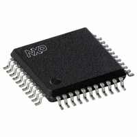
TDA9874AH/V2,557 NXP Semiconductors, TDA9874AH/V2,557 Datasheet - Page 34

TDA9874AH/V2,557
Manufacturer Part Number
TDA9874AH/V2,557
Description
IC SOUND DEMOD/DECODE 44PQFP
Manufacturer
NXP Semiconductors
Type
Demodulatorr
Datasheet
1.TDA9874AHV2557.pdf
(68 pages)
Specifications of TDA9874AH/V2,557
Applications
TV
Mounting Type
Surface Mount
Package / Case
44-QFP
Lead Free Status / RoHS Status
Lead free / RoHS Compliant
Other names
935263704557
TDA9874AHB
TDA9874AHB
TDA9874AHB
TDA9874AHB
Available stocks
Company
Part Number
Manufacturer
Quantity
Price
Company:
Part Number:
TDA9874AH/V2,557
Manufacturer:
NXP Semiconductors
Quantity:
10 000
Philips Semiconductors
7.3.14
When the auto-mute function is enabled
(see Section 7.3.12) and the NICAM bit error count is
lower than the value contained in this register, the NICAM
signal is selected (again) for reproduction; see also
Section 7.3.15.
The default setting after Power-on reset is 0001 0100.
Table 41 NICAM lower error limit register
7.3.15
When the auto-mute function is enabled and the NICAM bit
error count is higher than the value contained in this
register, the signal of the first sound carrier (i.e. FM mono
or AM sound) or the analog mono input is selected for
reproduction.
Table 43 Audio mute control register (subaddress 18)
Table 44 Description of the audio mute control register bits
2000 Aug 04
B7
Digital TV sound demodulator/decoder
7
BIT
7
1
7
6
5
4
3
2
1
0
NICAM L
NICAM U
B6
(subaddress 16)
6
MUTMOUT
B5
MUTSOUT
5
SYMBOL
OWER
MUTI
MUTI
PPER
6
2
2
B4
E
E
4
S
S
RROR
RROR
this bit is not used and should be set to logic 1
Mute I
these bits are not used and should be set to logic 1
Mute Stereo Output: if bit MUTSOUT = 1 the analog stereo output is muted
Mute Mono Output: if bit MUTMOUT = 1 the analog mono output is muted
this bit is not used and should be set to logic 1
B3
L
L
3
IMIT
IMIT
5
1
2
R
R
S-bus output: if bit MUTI
B2
EGISTER
EGISTER
2
B1
1
(NUELR)
(NLELR)
4
1
B0
0
34
The difference between the upper and lower error limit
constitutes a hysteresis to avoid frequent switching
between NICAM and the program on the 1st sound carrier.
The default setting after Power-on reset is 0101 0000.
Table 42 NICAM upper error limit register
7.3.16
Only bits 6, 2 and 1 are used. When any of these bits is set
to logic 1, the corresponding pair of output channels will be
muted. A bit set to logic 0 allows normal signal output.
The unused bits should be set to logic 1
The default setting after Power-on reset is 1111 1111.
2
S = 1 the I
B7
7
3
1
DESCRIPTION
A
B6
(subaddress 17)
6
UDIO
2
S-bus output is muted
MUTSOUT
M
B5
5
UTE
2
C
ONTROL
B4
4
MUTMOUT
B3
R
3
EGISTER
1
Product specification
B2
TDA9874A
2
(AMCONR)
B1
1
0
1
B0
0


