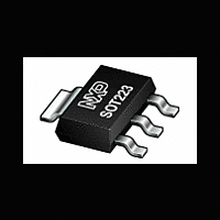
BT134W-600 NXP Semiconductors, BT134W-600 Datasheet - Page 4

BT134W-600
Manufacturer Part Number
BT134W-600
Description
Planar passivated four quadrant triac in a SOT223 surface-mountable plastic package intended for use in applications requiring high bidirectional transient and blocking voltage capability and high thermal cycling performance
Manufacturer
NXP Semiconductors
Datasheet
1.BT134W-600.pdf
(9 pages)
Available stocks
Company
Part Number
Manufacturer
Quantity
Price
Company:
Part Number:
BT134W-600135
Manufacturer:
NXP Semiconductors
Quantity:
60 088
Part Number:
BT134W-600D
Manufacturer:
NXP/恩智浦
Quantity:
20 000
Company:
Part Number:
BT134W-600D115
Manufacturer:
NXP Semiconductors
Quantity:
60 711
Company:
Part Number:
BT134W-600E
Manufacturer:
PHI
Quantity:
1 000
Part Number:
BT134W-600E
Manufacturer:
PHILIPS/飞利浦
Quantity:
20 000
September 1997
Triacs
Fig.1. Maximum on-state dissipation, P
on-state current, I
on-state current I
Fig.2. Maximum permissible non-repetitive peak
Fig.3. Maximum permissible non-repetitive peak
1000
12
10
1.4
1.2
0.8
0.6
0.4
0.2
on-state current I
Semiconductor
100
8
6
4
2
0
1
0
10
1
ITSM / A
0
1
10us
Ptot / W
ITSM / A
T2- G+ quadrant
sinusoidal currents, t
sinusoidal currents, f = 50 Hz.
0.2
100us
dI /dt limit
T
T(RMS)
10
Number of cycles at 50Hz
TSM
0.4
1
TSM
, versus number of cycles, for
, where α = conduction angle.
IT(RMS) / A
, versus pulse width t
BT134W
BT134W
BT134W
0.6
1ms
T / s
I
T
I
Tj initial = 25 C max
T
Tj initial = 25 C max
p
0.8
100
≤ 20ms.
T
10ms
T
Tsp(max) / C
tot
1
120
90
60
30
I TSM
, versus rms
I TSM
= 180
time
time
p
100ms
, for
1.2
1000
104
107
110
113
116
119
122
125
3
Fig.5. Maximum permissible repetitive rms on-state
current I
V
1.2
0.8
0.6
0.4
0.2
Fig.4. Maximum permissible rms current I
GT
1
0
1.5
0.5
1.6
1.4
1.2
0.8
0.6
0.4
-50
0.01
(T
2
1
0
IT(RMS) / A
1
-50
IT(RMS) / A
VGT(25 C)
j
Fig.6. Normalised gate trigger voltage
)/ V
VGT(Tj)
versus solder point temperature T
T(RMS)
currents, f = 50 Hz; T
GT
(25˚C), versus junction temperature T
, versus surge duration, for sinusoidal
0
0
0.1
surge duration / s
BT134W
BT134W
Tsp / C
BT136
Tj / C
50
50
sp
BT134W series
Product specification
≤ 108˚C.
1
100
100
108 C
sp
.
Rev 1.200
T(RMS)
150
10
150
,
j
.


