ISL55142IRZ Intersil, ISL55142IRZ Datasheet - Page 11
ISL55142IRZ
Manufacturer Part Number
ISL55142IRZ
Description
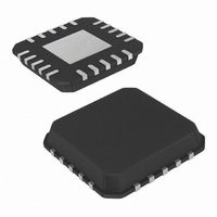
IC COMP CMOS HS 18V 20-QFN
Manufacturer
Intersil
Type
Windowr
Datasheet
1.ISL55141IVZ.pdf
(14 pages)
Specifications of ISL55142IRZ
Number Of Elements
2
Voltage - Supply
10 V ~ 18 V
Mounting Type
Surface Mount
Package / Case
20-VQFN Exposed Pad, 20-HVQFN, 20-SQFN, 20-DHVQFN
Lead Free Status / RoHS Status
Lead free / RoHS Compliant


Package Outline Drawing
M14.173
14 LEAD THIN SHRINK SMALL OUTLINE PACKAGE (TSSOP)
Rev 3, 10/09
6.40
0.20 C B A
4.40 ±0.10
2
SEATING
PLANE
C
(0.65 TYP)
(5.65)
0.10 C
TYPICAL RECOMMENDED LAND PATTERN
3
H
14
1
11
5.00 ±0.10
SIDE VIEW
TOP VIEW
0.65
1
0.25 +0.05/-0.06
0.10
3
0.05
8
7
ISL55141, ISL55142, ISL55143
CBA
A
I.D. MARK
(0.35 TYP)
PIN #1
1.20 MAX
(1.45)
B
5
NOTES:
1. Dimension does not include mold flash, protrusions or gate burrs.
2. Dimension does not include interlead flash or protrusion. Interlead
3. Dimensions are measured at datum plane H.
4. Dimensioning and tolerancing per ASME Y14.5M-1994.
5. Dimension does not include dambar protrusion. Allowable protrusion
6. Dimension in ( ) are for reference only.
7. Conforms to JEDEC MO-153, variation AB-1.
Mold flash, protrusions or gate burrs shall not exceed 0.15 per side.
flash or protrusion shall not exceed 0.25 per side.
shall be 0.80mm total in excess of dimension at maximum material
condition. Minimum space between protrusion and adjacent lead is 0.07mm.
0.90 +0.15/-0.10
0.15 MAX
0.05 MIN
DETAIL "X"
SEE
0.09-0.20
DETAIL "X"
END VIEW
1.00 REF
GAUGE
PLANE
0.60 ±0.15
0°-8°
March 1, 2011
0.25
FN6230.2
Related parts for ISL55142IRZ
Image
Part Number
Description
Manufacturer
Datasheet
Request
R

Part Number:
Description:
Intersil Corporation [CMOS Serial Controller Interface]
Manufacturer:
Intersil Corporation
Datasheet:
Part Number:
Description:
Manufacturer:
Intersil Corporation
Datasheet:
Part Number:
Description:
357-036-542-201 CARDEDGE 36POS DL .156 BLK LOPRO
Manufacturer:
Intersil Corporation
Datasheet:
Part Number:
Description:
1024-Word x 4-Bit LSI Static RAM
Manufacturer:
Intersil Corporation
Datasheet:
Part Number:
Description:
General Purpose NPN Transistor Arrays FN341.4
Manufacturer:
Intersil Corporation
Datasheet:
Part Number:
Description:
CMOS 16-Bit Microprocessor
Manufacturer:
Intersil Corporation
Datasheet:
Part Number:
Description:
Manufacturer:
Intersil Corporation
Datasheet:
Part Number:
Description:
Manufacturer:
Intersil Corporation
Datasheet:
Part Number:
Description:
Manufacturer:
Intersil Corporation
Datasheet:
Part Number:
Description:
Manufacturer:
Intersil Corporation
Datasheet:
Part Number:
Description:
CMOS 6-Bit Latch and Decoder Memory Interfaces
Manufacturer:
Intersil Corporation
Datasheet:
Part Number:
Description:
CA3046General Purpose NPN Transistor Arrays
Manufacturer:
Intersil Corporation
Datasheet:
Part Number:
Description:
Manufacturer:
Intersil Corporation
Datasheet:
Part Number:
Description:
TR909 DLC/FLC SLIC with Low Power Standby
Manufacturer:
Intersil Corporation
Datasheet:
Part Number:
Description:
Manufacturer:
Intersil Corporation
Datasheet: