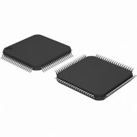
TDA9981BHL/15/C1;5 NXP Semiconductors, TDA9981BHL/15/C1;5 Datasheet - Page 19

TDA9981BHL/15/C1;5
Manufacturer Part Number
TDA9981BHL/15/C1;5
Description
IC HDMI TX 150MHZ 80-LQFP
Manufacturer
NXP Semiconductors
Type
Transmitterr
Datasheet
1.TDA9981BHL15C15.pdf
(41 pages)
Specifications of TDA9981BHL/15/C1;5
Applications
Recorders, Set-Top Boxes
Mounting Type
Surface Mount
Package / Case
80-LQFP
Lead Free Status / RoHS Status
Lead free / RoHS Compliant
Other names
935286062557
NXP Semiconductors
TDA9981B_1
Product data sheet
8.10 I
8.6 Color space converter
8.7 Downsampler
8.8 Audio input format
8.9 S/PDIF
The color space converter is used to convert input video data from one type to another
color space (RGB to YCbCr and YCbCr to RGB). This block can be bypassed and each
coefficient is programmable via the I
This block works only with YCbCr input format; these filters downsample the C
signals by a factor 2. A delay is added on the G/Y channel, which corresponds to the
pipeline delay of the filters, to put the Y channel in phase with the C
The TDA9981B is compatible with HDMI 1.2a (DVD support). The TDA9981B can carry
audio in I
S/PDIF or I
used at a time: either S/PDIF or I
Table 15.
All audio ports are LV-TTL compatible.
The audio port AP6 is used for the S/PDIF feature. In this format the TDA9981B supports
2-channel uncompressed PCM data (IEC 60958) layout 0 or compressed bit stream up to
8 multichannels (Dolby Digital, DTS, AC-3, etc.) layout 1. The TDA9981B is able to
recover the original clock from the S/PDIF signal (no need for an external clock). In
addition it can also use an external clock (MCLK) to decode the S/PDIF signal.
The TDA9981B supports the NXP I
channels (AP1 to AP4), which enable 8 uncompressed audio channels to be carried. The
I
Audio port
AP0
AP1
AP2
AP3
AP4
AP5
AP6
AP7
ACLK
2
2
C
C
S-bus input interface receives an I
Y \G
S-bus
B
R
\R
\B
=
2
S-bus format (one stereo up to four stereo channels) or in S/PDIF format.
Audio port configuration
2
C
C
C
S-bus format can be selected via the I
11
21
31
C
C
C
12
22
32
I
WS (word select)
I
I
I
I
MCLK (master clock for S/PDIF)
S/PDIF input
AUX (internal test)
SCK (I
C
C
C
2
2
2
2
2
S-bus and S/PDIF input configuration
S-bus port 0
S-bus port 1
S-bus port 2
S-bus port 3
13
23
33
Rev. 01 — 4 July 2008
2
S-bus clock)
R\C
B\C
G\Y
B
R
2
S-bus.
+
2
2
2
S-bus format. There are four I
S-bus signal including serial data, word select and
C-bus register.
Oin
Oin
Oin
Table 15
R\C
B\C
G\Y
B
R
+
2
shows the audio port allocation.
Oout
Oout
150 MHz pixel rate HDMI transmitter
C-bus. Only one audio format can be
Oout
C
C
Y \G
B
R
\R
\B
2
S-bus stereo input
TDA9981B
B
-C
© NXP B.V. 2008. All rights reserved.
R
channel.
B
and C
19 of 41
R


