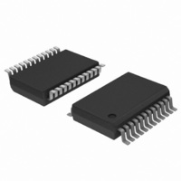
TDA9884TS/V1,112 NXP Semiconductors, TDA9884TS/V1,112 Datasheet - Page 27

TDA9884TS/V1,112
Manufacturer Part Number
TDA9884TS/V1,112
Description
IC IF-PLL I2C-BUS DEMOD 24-SSOP
Manufacturer
NXP Semiconductors
Type
Demodulatorr
Datasheet
1.TDA9884TSV1112.pdf
(58 pages)
Specifications of TDA9884TS/V1,112
Package / Case
*
Applications
Mobile Reception
Mounting Type
Surface Mount
Maximum Operating Temperature
+ 70 C
Minimum Operating Temperature
- 20 C
Mounting Style
SMD/SMT
Lead Free Status / RoHS Status
Lead free / RoHS Compliant
Other names
935270308112
TDA9884TS/V1
TDA9884TS/V1
TDA9884TS/V1
TDA9884TS/V1
Philips Semiconductors
Table 25.
V
f
IF input from 50
video signal in accordance with “ITU-T J.63 line 17 and line 330” or “NTC-7 Composite”; measurements taken in test circuit of
Figure
TDA9884_2
Product data sheet
Symbol
I
V
t
t
Tuner AGC (pin TAGC); see
V
V
V
V
QV
V
V
SC
i
d1
d2
P
QV
i
i(VIF)(start1)(rms)
i(VIF)(start2)(rms)
i(SIF)(start1)(rms)
i(SIF)(start2)(rms)
o
sat
= 5 V; T
= 33.4 MHz; PC/SC = 13 dB; f
TOP
TOP
23; unless otherwise specified.
/ T
amb
Characteristics
= 25 C; see
via broadband transformer 1 : 1; video modulation DSB; residual carrier for B/G is 10 % and for L is 3 %;
Parameter
input current
input voltage
switching delay for
external AGC = ON
switching delay for
external AGC = OFF
VIF input signal
voltage for minimum
starting point of
tuner takeover at
pins VIF1 and VIF2
(RMS value)
VIF input signal
voltage for maximum
starting point of
tuner takeover at
pins VIF1 and VIF2
(RMS value)
SIF input signal
voltage for minimum
starting point of
tuner takeover at
pins SIF1 and SIF2
(RMS value)
SIF input signal
voltage for maximum
starting point of
tuner takeover at
pins SIF1 and SIF2
(RMS value)
tuner takeover point
accuracy
takeover point
variation with
temperature
permissible output
voltage
saturation voltage
Table 27
…continued
Figure
mod
for input frequencies; B/G standard is used for the specification (f
= 400 Hz); input level V
4,
Figure 10
Conditions
bit E5 = 1; bit E7 = 1;
V
bit E5 = 1; bit E7 = 1;
pin AGCSW open-circuit
bit E5 = 1; bit E7 = 1;
V
bit E5 = 1; bit E7 = 1;
V
I
R
and 15 dB via I
(see
I
or no R
I
true split sound mode;
I
R
and 15 dB via I
(see
true split sound mode;
I
or no R
I
I
R
and 0 dB via I
(see
I
from external source
I
TAGC
TAGC
2
TAGC
TAGC
2
TAGC
TAGC
TAGC
AGCSW
AGCSW
AGCSW
C-bus (see
C-bus (see
TOP
TOP
TOP
normal mode
true split sound mode
Table
Table
Table
= 120 A;
= 22 k or no R
= 120 A; R
= 120 A;
= 22 k or no R
= 120 A; R
= 120 A;
= 10 k ; or no R
= 120 A
= 450 A
and
Rev. 02 — 12 May 2006
TOP
TOP
= 0 V
= 2.5 V
= 0.3 V
16)
16)
16)
Figure 11
and +15 dB via
and +15 dB via
Table
Table
2
I
C-bus
2
C-bus controlled multistandard alignment-free IF-PLL
2
2
i(VIF)
C-bus
C-bus
TOP
TOP
16)
16)
= 10 mV (RMS) (sync level for B/G; peak white level for L);
= 0
= 0
TOP
TOP
TOP
Min
-
V
-
-
-
45
-
22.5
7
4
-
-
-
P
1.7 -
© Koninklijke Philips Electronics N.V. 2006. All rights reserved.
Typ
5
-
-
2
90
1
45
17
9
0.03
-
-
PC
TDA9884
Max
-
-
150
150
5
-
2.5
-
43
22
0.07
8.8
0.5
= 38.9 MHz;
Unit
V
ns
ns
mV
mV
mV
mV
mV
mV
dB/K
V
V
A
27 of 58


