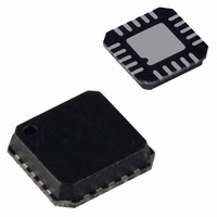
AD8324ACP Analog Devices Inc, AD8324ACP Datasheet - Page 14

AD8324ACP
Manufacturer Part Number
AD8324ACP
Description
IC LINE DRIVER CATV 3.3V 20LFCSP
Manufacturer
Analog Devices Inc
Type
Line Driver, Transmitterr
Datasheet
1.AD8324ACPZ.pdf
(16 pages)
Specifications of AD8324ACP
Applications
Modems, CATV
Mounting Type
Surface Mount
Package / Case
20-LFCSP
Lead Free Status / RoHS Status
Lead free / RoHS Compliant
Available stocks
Company
Part Number
Manufacturer
Quantity
Price
Company:
Part Number:
AD8324ACPZ
Manufacturer:
MSTAR
Quantity:
2 356
Part Number:
AD8324ACPZ
Manufacturer:
ADI/亚德诺
Quantity:
20 000
Part Number:
AD8324ACPZ-REEL
Manufacturer:
ADI/亚德诺
Quantity:
20 000
Company:
Part Number:
AD8324ACPZ-REEL7
Manufacturer:
PWRI
Quantity:
2 582
AD8324
OVERSHOOT ON PC PRINTER PORTS
The data lines on some PC parallel printer ports have excessive
overshoot, which may cause communications problems when
presented to the CLK pin of the AD8324. The evaluation board
was designed to accommodate a series resistor and shunt
capacitor (R9 and C5 in Figure 29) to filter the CLK signal if
required. For parallel ports with logic levels above 3.3 V, R9 and
C5 may be used as an attenuator.
INSTALLING VISUAL BASIC CONTROL SOFTWARE
Install the CabDrive_24 software by running the setup.exe file
on disk one of the AD8324 evaluation software. Follow the on-
screen directions and insert disk two when prompted. Choose
the installation directory and then select the icon in the upper
left to complete the installation.
RUNNING AD8324 SOFTWARE
To load the control software, go to START, PROGRAMS,
CABDRIVE_24 or select the AD8324.exe file from the installed
directory. Once loaded, select the proper parallel port to
communicate with the AD8324 (Figure 27).
Figure 27. Parallel Port Selection
Rev. A | Page 14 of 16
CONTROLLING GAIN/ATTENUATION
OF THE AD8324
The slide bar controls the gain/attenuation of the AD8324,
which is displayed in dB and in V/V. The gain scales 1 dB per
LSB. The gain code from the position of the slide bar is
displayed in decimal, binary, and hexadecimal (Figure 28).
TRANSMIT ENABLE AND SLEEP MODE
The Transmit Enable and Transmit Disable buttons select the
mode of operation of the AD8324 by asserting logic levels on
the asynchronous TXEN pin. The Transmit Disable button
applies Logic 0 to the TXEN pin, disabling forward transmis-
sion. The Transmit Enable button applies Logic 1 to the TXEN
pin, enabling the AD8324 for forward transmission. Checking
the Enable SLEEP Mode checkbox applies Logic 0 to the asyn-
chronous SLEEP pin, setting the AD8324 for SLEEP mode.
MEMORY FUNCTIONS
The Memory section of the software provides a way to alternate
between two gain settings. The X–>M1 button stores the
current value of the gain slide bar into memory, while the RM1
button recalls the stored value, returning the gain slide bar to
the stored level. The same applies to the X–>M2 and RM2
buttons.
Figure 28. Control Software Interface


