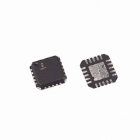
EL9115IL-T13 Intersil, EL9115IL-T13 Datasheet - Page 8

EL9115IL-T13
Manufacturer Part Number
EL9115IL-T13
Description
IC ANALOG DELAY LINE TRPL 20-QFN
Manufacturer
Intersil
Type
Video Delay Liner
Datasheet
1.EL9115ILZ-T13.pdf
(9 pages)
Specifications of EL9115IL-T13
Applications
Analog Beamforming, Skew Control
Mounting Type
Surface Mount
Package / Case
20-VQFN Exposed Pad, 20-HVQFN, 20-SQFN, 20-DHVQFN
Lead Free Status / RoHS Status
Contains lead / RoHS non-compliant
Signals A and B are derived from the video input by
comparing the video signal with a slicing level, which is set by
an internal DAC. This enables the delay to be measured
either from the rising edges of sync-like signals encoded on
top of the video or from a dedicated set-up signal. The outputs
can be used to set the correct delays for the signals received.
The DAC level is set through the serial input by bits 1
through 4 directed to the test register (00).
Test Mode
Bit zero of the test register is set to 0 for normal operation. If
it is set to 1 then the device is in Test Mode. In Test Mode,
the DAC voltage is directed to the Green channel output,
while for the Red and Blue channels, the test outputs are
now pulses of current which are generated by looking at the
delay between the input and output of the channel. They
thus enable the delay to be measured.
VIDEO IN
4
FIGURE 15. DELAY DETECTOR
OUTPUT
A
B
SLICING LEVEL
8
COMPARATORS
A
B
EL9115
NOTE: Test Register word = 000wxyzt. If t = 1 test mode else
normal. wxyz fed to DAC. z is LSB
wxyz
1000
1001
1010
1011
1100
1101
0000
0001
0010
0011
0100
0101
0110
1110
1111
0111
TABLE 2.
DAC/mV
-400
-350
-300
-250
-200
-150
-100
100
150
200
250
300
350
-50
50
0
September 22, 2009
FN7441.5


