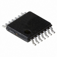
74HCT126PW,112 NXP Semiconductors, 74HCT126PW,112 Datasheet - Page 6

74HCT126PW,112
Manufacturer Part Number
74HCT126PW,112
Description
IC BUFFER DVR TRI-ST QD 14TSSOP
Manufacturer
NXP Semiconductors
Series
74HCTr
Datasheet
1.74HC126N652.pdf
(6 pages)
Specifications of 74HCT126PW,112
Logic Type
Buffer/Line Driver, Non-Inverting
Number Of Elements
4
Number Of Bits Per Element
1
Current - Output High, Low
2mA, 2mA
Voltage - Supply
4.5 V ~ 5.5 V
Mounting Type
Surface Mount
Package / Case
14-TSSOP
Logic Family
HCT
Logical Function
Buffer/Line Driver
Number Of Elements
4
Number Of Channels
4
Number Of Inputs
4
Number Of Outputs
4
Operating Supply Voltage (typ)
5V
Package Type
TSSOP
Output Type
3-State
Polarity
Non-Inverting
Propagation Delay Time
42ns
High Level Output Current
-6mA
Low Level Output Current
6mA
Operating Supply Voltage (max)
5.5V
Operating Supply Voltage (min)
4.5V
Quiescent Current
8uA
Technology
CMOS
Pin Count
14
Mounting
Surface Mount
Operating Temp Range
-40C to 125C
Operating Temperature Classification
Automotive
Lead Free Status / RoHS Status
Lead free / RoHS Compliant
Operating Temperature
-
Lead Free Status / Rohs Status
Compliant
Other names
74HCT126PW
74HCT126PW
935183550112
74HCT126PW
935183550112
Philips Semiconductors
AC WAVEFORMS
PACKAGE OUTLINES
See
December 1990
Quad buffer/line driver; 3-state
(1) HC : V
(1) HC : V
“74HC/HCT/HCU/HCMOS Logic Package Outlines”
Fig.6 Waveforms showing the input (nA) to output (nY) propagation delays and the output transition times.
HCT: V
HCT: V
M
M
M
M
= 50%; V
= 50%; V
= 1.3 V; V
= 1.3 V; V
I
I
I
I
= GND to V
= GND to V
= GND to 3 V.
= GND to 3 V.
Fig.7 Waveforms showing the 3-state enable and disable times.
CC
CC
.
.
.
6
74HC/HCT126
Product specification


