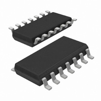
74HCU04D,653 NXP Semiconductors, 74HCU04D,653 Datasheet - Page 5

74HCU04D,653
Manufacturer Part Number
74HCU04D,653
Description
IC INVERTER HEX UNBUFFER 14SOIC
Manufacturer
NXP Semiconductors
Series
74HCUr
Datasheet
1.74HCU04D653.pdf
(7 pages)
Specifications of 74HCU04D,653
Number Of Circuits
6
Logic Type
Inverter
Package / Case
14-SOIC (3.9mm Width), 14-SOL
Number Of Inputs
1
Current - Output High, Low
5.2mA, 5.2mA
Voltage - Supply
2 V ~ 6 V
Operating Temperature
-40°C ~ 125°C
Mounting Type
Surface Mount
Logic Family
74HCU
High Level Output Current
- 5.2 mA
Low Level Output Current
5.2 mA
Propagation Delay Time
70 ns, 14 ns, 12 ns
Supply Voltage (max)
6 V
Supply Voltage (min)
2 V
Maximum Operating Temperature
+ 125 C
Minimum Operating Temperature
- 40 C
Mounting Style
SMD/SMT
Operating Supply Voltage
2 V to 6 V
Lead Free Status / RoHS Status
Lead free / RoHS Compliant
Lead Free Status / RoHS Status
Lead free / RoHS Compliant, Lead free / RoHS Compliant
Other names
568-1571-2
74HCU04D-T
933714000653
74HCU04D-T
933714000653
Philips Semiconductors
AC CHARACTERISTICS FOR 74HCU
GND = 0 V; t
AC WAVEFORMS
TYPICAL TRANSFER
CHARACTERISTICS
September 1993
t
t
PHL
THL
SYMBOL
(1) V
Fig.6 Waveforms showing the data input (nA) to data output (nY) propagation delays and the output transition times.
Fig.7
Hex inverter
/ t
/ t
M
TLH
PLH
= 50%; V
_____ V
_ _ _ _ I
I
O
= 0; V
r
propagation delay
output transition time
= t
I
= GND to V
nA to nY
f
PARAMETER
D
O;
CC
= 6 ns; C
(drain current);
= 6.0 V.
CC
.
L
= 50 pF
min.
Fig.8
19
7
6
19
7
6
typ.
+25
70
14
12
75
15
13
______ V
I
max. min. max.
_ _ _ _ I
O
= 0; V
T
74HCU
amb
-40 to +85
CC
D
5
O
(drain current);
;
( C)
= 4.5 V.
90
18
15
95
19
16
min.
40 to +125
105
21
18
110
22
19
max.
Fig.9
ns
ns
UNIT
_____ V
_ _ _ _ I
I
O
= 0; V
2.0
4.5
6.0
2.0
4.5
6.0
V
(V)
TEST CONDITIONS
CC
Product specification
D
O
CC
;
Fig.6
Fig.6
(drain current);
74HCU04
WAVEFORMS
= 2.0 V.


