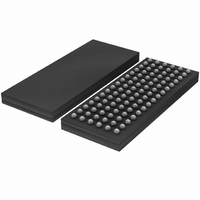
SSTUH32864EC,557 NXP Semiconductors, SSTUH32864EC,557 Datasheet - Page 11

SSTUH32864EC,557
Manufacturer Part Number
SSTUH32864EC,557
Description
IC BUFFER 1.8V 1/14BIT SOT536-1
Manufacturer
NXP Semiconductors
Datasheet
1.SSTUH32864ECG518.pdf
(20 pages)
Specifications of SSTUH32864EC,557
Logic Type
1:2 Configurable Registered Buffer
Supply Voltage
1.7 V ~ 1.9 V
Number Of Bits
25, 14
Operating Temperature
0°C ~ 70°C
Mounting Type
Surface Mount
Package / Case
96-LFBGA
Lead Free Status / RoHS Status
Lead free / RoHS Compliant
Other names
935277951557
SSTUH32864EC
SSTUH32864EC
SSTUH32864EC
SSTUH32864EC
Philips Semiconductors
Table 7:
Recommended operating conditions; T
See
[1]
[2]
[3]
Table 8:
Recommended operating conditions; T
Class I, V
[1]
[2]
Table 9:
Recommended operating conditions, unless otherwise specified. V
9397 750 14137
Product data sheet
Symbol
f
t
t
t
t
t
Symbol
f
t
t
t
Symbol
dV/dt_r
dV/dt_f
dV/dt_
clock
W
ACT
INACT
su
h
MAX
PDM
PDMSS
PHL
This parameter is not necessarily production tested.
Data inputs must be active below a minimum time of t
Data and clock inputs must be held at valid levels (not floating) a minimum time of t
Includes 350 ps of test-load transmission line delay.
This parameter is not necessarily production tested.
Figure 6
ref
Timing requirements
Switching characteristics
Output edge rates
= V
through
Parameter
clock frequency
pulse duration, CK, CK HIGH or
LOW
differential inputs active time
differential inputs inactive time
setup time
hold time
Parameter
maximum input clock frequency
propagation delay
propagation delay, simultaneous
switching
propagation delay
Parameter
rising edge slew rate
falling edge slew rate
absolute difference between dV/dt_r
and dV/dt_f
TT
= V
Figure
DD
0.5 and C
11.
L
= 10 pF; unless otherwise specified. See
amb
amb
= 0 C to +70 C; V
= 0 C to +70 C; V
Rev. 01 — 22 April 2005
Conditions
DCS before CK , CK ,
CSR HIGH
DCS before CK , CK ,
CSR LOW
CSR, DODT, DCKE, and
data before CK , CK
DCS, CSR, DODT, DCKE,
and data after CK , CK
Conditions
CK and CK to output
CK and CK to output
RESET to output
Conditions
ACT(max)
after RESET is taken HIGH.
DD
DD
= 1.8 V
= 1.8 V
DD
= 1.8 V
1.8 V high output drive DDR registered buffer
0.1 V; unless otherwise specified.
0.1 V;
INACT(max)
0.1 V
Figure 6
[1] [2]
[1] [3]
[1] [2]
[1]
after RESET is taken LOW.
Min
-
1
-
-
0.7
0.5
0.5
0.5
Min
450
1.41
-
-
Min
1
1
-
through
© Koninklijke Philips Electronics N.V. 2005. All rights reserved.
SSTUH32864
Typ
-
-
-
-
-
-
-
-
Figure
Typ
-
-
-
-
Typ
-
-
-
11.
Max
450
-
10
15
-
-
-
-
Max
-
1.8
2.0
3
Max
4
4
1
Unit
MHz
ns
ns
ns
ns
ns
ns
ns
Unit
MHz
ns
ns
ns
Unit
V/ns
V/ns
V/ns
11 of 20


