23K256-I/P Microchip Technology, 23K256-I/P Datasheet - Page 6
23K256-I/P
Manufacturer Part Number
23K256-I/P
Description
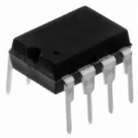
IC SRAM 256KBIT 20MHZ 8DIP
Manufacturer
Microchip Technology
Type
Synchronousr
Specifications of 23K256-I/P
Memory Size
256K (32K x 8)
Package / Case
8-DIP (0.300", 7.62mm)
Format - Memory
RAM
Memory Type
SRAM
Speed
20MHz
Interface
SPI Serial
Voltage - Supply
2.7 V ~ 3.6 V
Operating Temperature
-40°C ~ 85°C
Access Time
25 ns
Maximum Clock Frequency
20 MHz
Supply Voltage (max)
3.6 V
Supply Voltage (min)
2.7 V
Maximum Operating Current
10 mA
Maximum Operating Temperature
+ 85 C
Minimum Operating Temperature
- 40 C
Mounting Style
Through Hole
Number Of Ports
1
Operating Supply Voltage
3.3 V
Lead Free Status / RoHS Status
Lead free / RoHS Compliant
Lead Free Status / RoHS Status
Lead free / RoHS Compliant, Lead free / RoHS Compliant
Available stocks
Company
Part Number
Manufacturer
Quantity
Price
Company:

Part Number:
23K256-I/P
Manufacturer:
MCP
Quantity:
60
Company:
Part Number:
23K256-I/P
Manufacturer:
MICROCHIP
Quantity:
12 000


23X256
2.0
2.1
The 23X256 is a 32,768-byte Serial SRAM designed to
interface directly with the Serial Peripheral Interface
(SPI) port of many of today’s popular microcontroller
families, including Microchip’s PIC
may also interface with microcontrollers that do not
have a built-in SPI port by using discrete I/O lines
programmed properly in firmware to match the SPI
protocol.
The 23X256 contains an 8-bit instruction register. The
device is accessed via the SI pin, with data being
clocked in on the rising edge of SCK. The CS pin must
be low and the HOLD pin must be high for the entire
operation.
Table 2-1
bytes and format for device operation. All instructions,
addresses and data are transferred MSB first, LSB last.
Data (SI) is sampled on the first rising edge of SCK
after CS goes low. If the clock line is shared with other
peripheral devices on the SPI bus, the user can assert
the HOLD input and place the 23X256 in ‘HOLD’ mode.
After releasing the HOLD pin, operation will resume
from the point when the HOLD was asserted.
2.2
The 23A256/23K256 has three modes of operation that
are selected by setting bits 7 and 6 in the STATUS
register. The modes of operation are Byte, Page and
Burst.
Byte Operation – is selected when bits 7 and 6 in the
STATUS register are set to 00. In this mode, the read/
write operations are limited to only one byte. The
Command followed by the 16-bit address is clocked into
the device and the data to/from the device is transferred
on the next 8 clocks
Page Operation – is selected when bits 7 and 6 in the
STATUS register are set to 10. The 23A256/23K256 has
1024 pages of 32 Bytes. In this mode, the read and write
operations are limited to within the addressed page (the
address is automatically incremented internally). If the
data being read or written reaches the page boundary,
then the internal address counter will increment to the
start of the page
Sequential Operation – is selected when bits 7 and 6
in the STATUS register are set to 01. Sequential opera-
tion allows the entire array to be written to and read
from. The internal address counter is automatically
incremented and page boundaries are ignored. When
the internal address counter reaches the end of the
array, the address counter will roll over to 0x0000
(Figure
DS22100E-page 6
2-5,
FUNCTIONAL DESCRIPTION
Principles of Operation
Modes of Operation
contains a list of the possible instruction
Figure
(Figure
2-6).
(Figure
2-3,
2-1,
Figure
Figure
®
2-4).
microcontrollers. It
2-2).
2.3
The device is selected by pulling CS low. The 8-bit
READ instruction is transmitted to the 23X256 followed
by the 16-bit address, with the first MSB of the address
being a “don’t care” bit. After the correct READ
instruction and address are sent, the data stored in the
memory at the selected address is shifted out on the
SO pin.
If operating in Page mode, after the first byte of data is
shifted out, the next memory location on the page can
be read out by continuing to provide clock pulses. This
allows for 32 consecutive address reads. After the
32nd address read the internal address counter wraps
back to the byte 0 address in that page.
If operating in Sequential mode, the data stored in the
memory at the next address can be read sequentially
by continuing to provide clock pulses. The internal
Address Pointer is automatically incremented to the
next higher address after each byte of data is shifted
out. When the highest address is reached (7FFFh),
the address counter rolls over to address 0000h,
allowing the read cycle to be continued indefinitely.
The read operation is terminated by raising the CS pin
(Figure
2.4
Prior to any attempt to write data to the 23X256, the
device must be selected by bringing CS low.
Once the device is selected, the Write command can
be started by issuing a WRITE instruction, followed by
the 16-bit address, with the first MSB of the address
being a “don’t care” bit, and then the data to be written.
A write is terminated by the CS being brought high.
If operating in Page mode, after the initial data byte is
shifted in, additional bytes can be shifted into the
device.
incremented. This operation can continue for the entire
page (32 Bytes) before data will start to be overwritten.
If operating in Sequential mode, after the initial data
byte is shifted in, additional bytes can be clocked into
the device. The internal Address Pointer is automati-
cally incremented. When the Address Pointer reaches
the highest address (7FFFh), the address counter rolls
over to (0000h). This allows the operation to continue
indefinitely, however, previous data will be overwritten.
2-1).
Read Sequence
Write Sequence
The
Address
2010 Microchip Technology Inc.
Pointer
is
automatically
Related parts for 23K256-I/P
Image
Part Number
Description
Manufacturer
Datasheet
Request
R

Part Number:
Description:
IC SRAM 256KBIT 20MHZ 8SOIC
Manufacturer:
Microchip Technology
Datasheet:

Part Number:
Description:
256K SPI Bus Low-Power Serial SRAM
Manufacturer:
MICROCHIP [Microchip Technology]
Datasheet:

Part Number:
Description:
IC SRAM 256KBIT 20MHZ 8TSSOP
Manufacturer:
Microchip Technology
Datasheet:
Part Number:
Description:
IC SRAM 256KBIT 20MHZ 8DIP
Manufacturer:
Microchip Technology
Datasheet:
Part Number:
Description:
IC SRAM 256KBIT 20MHZ 8TSSOP
Manufacturer:
Microchip Technology
Datasheet:

Part Number:
Description:
IC SRAM 256KBIT 20MHZ 8SOIC
Manufacturer:
Microchip Technology
Datasheet:

Part Number:
Description:
Manufacturer:
Microchip Technology Inc.
Datasheet:
Part Number:
Description:
Manufacturer:
Microchip Technology Inc.
Datasheet:
Part Number:
Description:
Manufacturer:
Microchip Technology Inc.
Datasheet:
Part Number:
Description:
Manufacturer:
Microchip Technology Inc.
Datasheet:
Part Number:
Description:
Manufacturer:
Microchip Technology Inc.
Datasheet:
Part Number:
Description:
Manufacturer:
Microchip Technology Inc.
Datasheet: