M27C512-15F6 STMicroelectronics, M27C512-15F6 Datasheet - Page 7
M27C512-15F6
Manufacturer Part Number
M27C512-15F6
Description
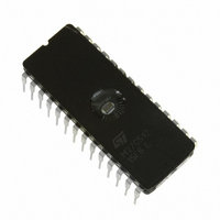
IC EPROM 512KBIT 150NS 28CDIP
Manufacturer
STMicroelectronics
Datasheets
1.M27C512-90B6.pdf
(22 pages)
2.M27C512-12F1.pdf
(10 pages)
3.M27C512-15F6.pdf
(22 pages)
Specifications of M27C512-15F6
Format - Memory
EPROMs
Memory Type
UV EPROM
Memory Size
512K (64K x 8)
Speed
150ns
Interface
Parallel
Voltage - Supply
4.5 V ~ 5.5 V
Operating Temperature
-40°C ~ 85°C
Package / Case
28-CDIP (0.600", 15.24mm) Window
Capacitance, Input
6 pF
Capacitance, Output
12 pF
Current, Input, Leakage
±10 μA (Read)
Current, Operating
30 mA (Read)
Current, Output, Leakage
±10 μA (Read)
Current, Supply
30 mA
Density
512K
Organization
64K×8
Package Type
FDIP28W
Temperature, Operating
0 to +70 °C
Temperature, Operating, Maximum
85 °C
Temperature, Operating, Minimum
-40 °C
Time, Access
100 ns
Time, Fall
≤20 ns
Time, Rise
≤20 ns
Voltage, Input, High
6 V (Read)
Voltage, Input, High Level
2 V (Min.)
Voltage, Input, Low
0.8 V (Read)
Voltage, Input, Low Level
-0.3 V (Min.)
Voltage, Output, High
4.3 V (Read)
Voltage, Output, Low
0.4 V (Read)
Voltage, Programmable
11.5 V (Min.)
Voltage, Supply
5 V
Interface Type
Parallel
Bus Type
Parallel
In System Programmable
In System/External
Access Time (max)
150ns
Reprogramming Technique
UV
Operating Supply Voltage (typ)
5V
Operating Supply Voltage (min)
4.5V
Operating Supply Voltage (max)
5.5V
Supply Current
50mA
Pin Count
28
Mounting
Through Hole
Operating Temp Range
-40C to 85C
Operating Temperature Classification
Industrial
Lead Free Status / RoHS Status
Lead free / RoHS Compliant
Other names
497-1676-5
Available stocks
Company
Part Number
Manufacturer
Quantity
Price
Company:

Part Number:
M27C512-15F6
Manufacturer:
SHARP
Quantity:
185
Part Number:
M27C512-15F6
Manufacturer:
ST
Quantity:
20 000


tion, a 4.7µF bulk electrolytic capacitor should be
used between V
es. The bulk capacitor should be located near the
power supply connection point.The purpose of the
bulk capacitor is to overcome the voltage drop
caused by the inductive effects of PCB traces.
Figure 6. Programming Flowchart
Programming
When delivered (and after each erasure for UV
EPROM), all bits of the M27C512 are in the '1'
state. Data is introduced by selectively program-
ming '0's into the desired bit locations. Although
only '0's will be programmed, both '1's and '0's can
be present in the data word. The only way to
change a '0' to a '1' is by die exposure to ultraviolet
light (UV EPROM). The M27C512 is in the pro-
gramming mode when V
E is pulsed to V
applied to 8 bits in parallel to the data output pins.
The levels required for the address and data in-
puts are TTL. V
0.25V. The M27C512 can use PRESTO IIB Pro-
gramming Algorithm that drastically reduces the
programming time (typically less than 6 seconds).
YES
NO
FAIL
= 25
++n
V CC = 6.25V, V PP = 12.75V
RESET MARGIN MODE
SET MARGIN MODE
IL
CC
CHECK ALL BYTES
NO
CC
. The data to be programmed is
2nd: V CC = 4.2V
E = 100 s Pulse
1st: V CC = 6V
and V
VERIFY
is specified to be 6.25V ±
n = 0
Addr
Last
PP
YES
YES
SS
input is at 12.75V and
for every eight devic-
NO
++ Addr
AI00738B
Nevertheless to achieve compatibility with all pro-
gramming equipments, PRESTO Programming
Algorithm can be used as well.
PRESTO IIB Programming Algorithm
PRESTO IIB Programming Algorithm allows the
whole array to be programmed with a guaranteed
margin, in a typical time of 6.5 seconds. This can
be achieved with STMicroelectronics M27C512
due to several design innovations described in the
M27C512 datasheet to improve programming effi-
ciency and to provide adequate margin for reliabil-
ity. Before starting the programming the internal
MARGIN MODE circuit is set in order to guarantee
that each cell is programmed with enough margin.
Then a sequence of 100µs program pulses are ap-
plied to each byte until a correct verify occurs. No
overprogram pulses are applied since the verify in
MARGIN MODE provides the necessary margin.
Program Inhibit
Programming of multiple M27C512s in parallel
with different data is also easily accomplished. Ex-
cept for E, all like inputs including GV
allel M27C512 may be common. A TTL low level
pulse applied to a M27C512's E input, with V
12.75V, will program that M27C512. A high level E
input inhibits the other M27C512s from being pro-
grammed.
Program Verify
A verify (read) should be performed on the pro-
grammed bits to determine that they were correct-
ly programmed. The verify is accomplished with G
at V
falling edge of E.
Electronic Signature
The Electronic Signature (ES) mode allows the
reading out of a binary code from an EPROM that
will identify its manufacturer and type. This mode
is intended for use by programming equipment to
automatically match the device to be programmed
with its corresponding programming algorithm.
The ES mode is functional in the 25°C ± 5°C am-
bient temperature range that is required when pro-
gramming the M27C512. To activate the ES
mode, the programming equipment must force
11.5V to 12.5V on address line A9 of the
M27C512. Two identifier bytes may then be se-
quenced from the device outputs by toggling ad-
dress line A0 from V
lines must be held at V
ture mode. Byte 0 (A0 = V
ufacturer code and byte 1 (A0 = V
identifier
M27C512, these two identifier bytes are given in
Table 3.
IL
. Data should be verified with t
and can be read-out on outputs Q7 to Q0.
code.
For
IL
IL
to V
the
during Electronic Signa-
IL
) represents the man-
IH
. All other address
STMicroelectronics
IH
ELQV
PP
) the device
M27C512
of the par-
after the
PP
7/22
at
Related parts for M27C512-15F6
Image
Part Number
Description
Manufacturer
Datasheet
Request
R

Part Number:
Description:
M27C512-15XF1512 Kbit (64K x8) UV EPROM and OTP EPROM
Manufacturer:
STMicroelectronics
Datasheet:
Part Number:
Description:
Manufacturer:
STMicroelectronics
Datasheet:
Part Number:
Description:
Manufacturer:
STMicroelectronics
Datasheet:

Part Number:
Description:
IC OTP 512KBIT 70NS 32PLCC
Manufacturer:
STMicroelectronics
Datasheet:

Part Number:
Description:
IC EPROM 512KBIT 70NS 28CDIP
Manufacturer:
STMicroelectronics
Datasheet:

Part Number:
Description:
IC EPROM 512KBIT 120NS 28CDIP
Manufacturer:
STMicroelectronics
Datasheet:
Part Number:
Description:
IC OTP 512KBIT 90NS 32PLCC
Manufacturer:
STMicroelectronics
Datasheet:
Part Number:
Description:
IC OTP 512KBIT 100NS 32PLCC
Manufacturer:
STMicroelectronics
Datasheet:
Part Number:
Description:
IC EPROM 512KBIT 150NS 28CDIP
Manufacturer:
STMicroelectronics
Datasheet:

Part Number:
Description:
IC EPROM 512KBIT 90NS 28CDIP
Manufacturer:
STMicroelectronics
Datasheet:
Part Number:
Description:
IC EPROM 512KBIT 45NS 28CDIP
Manufacturer:
STMicroelectronics
Datasheet:

Part Number:
Description:
IC EPROM 512KBIT 100NS 28CDIP
Manufacturer:
STMicroelectronics
Datasheet:

Part Number:
Description:
IC OTP 512KBIT 120NS 28DIP
Manufacturer:
STMicroelectronics
Datasheet: