AT24C64B-10TU-2.7 Atmel, AT24C64B-10TU-2.7 Datasheet - Page 5
AT24C64B-10TU-2.7
Manufacturer Part Number
AT24C64B-10TU-2.7
Description
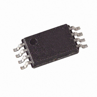
IC EEPROM 64KBIT 400KHZ 8TSSOP
Manufacturer
Atmel
Datasheet
1.AT24C64BN-10SU-2.7.pdf
(16 pages)
Specifications of AT24C64B-10TU-2.7
Format - Memory
EEPROMs - Serial
Memory Type
EEPROM
Memory Size
64K (8K x 8)
Speed
400kHz
Interface
I²C, 2-Wire Serial
Voltage - Supply
2.7 V ~ 5.5 V
Operating Temperature
-40°C ~ 85°C
Package / Case
8-TSSOP
Organization
8 Kbit x 8
Interface Type
2-Wire
Maximum Clock Frequency
400 KHz
Access Time
0.6 us
Supply Voltage (max)
5.5 V
Supply Voltage (min)
2.7 V
Maximum Operating Current
3 mA
Maximum Operating Temperature
+ 85 C
Mounting Style
SMD/SMT
Minimum Operating Temperature
- 40 C
Operating Supply Voltage
6.25 V
Lead Free Status / RoHS Status
Lead free / RoHS Compliant
Available stocks
Company
Part Number
Manufacturer
Quantity
Price

Part Number:
AT24C64B-10TU-2.7
Manufacturer:
ATMEL/爱特梅尔
Quantity:
20 000


5. Device Operation
3350E–SEEPR–9/07
CLOCK and DATA TRANSITIONS: The SDA pin is normally pulled high with an external
device. Data on the SDA pin may change only during SCL low time periods (refer to Data Valid-
ity timing diagram). Data changes during SCL high periods will indicate a start or stop condition
as defined below.
START CONDITION: A high-to-low transition of SDA with SCL high is a start condition which
must precede any other command (refer to Start and Stop Definition timing diagram).
STOP CONDITION: A low-to-high transition of SDA with SCL high is a stop condition. After a
read sequence, the stop command will place the EEPROM in a standby power mode (refer to
Start and Stop Definition timing diagram).
ACKNOWLEDGE: All addresses and data words are serially transmitted to and from the
EEPROM in 8-bit words. The EEPROM sends a zero during the ninth clock cycle to acknowl-
edge that it has received each word.
STANDBY MODE: The AT24C64B features a low power standby mode which is enabled: a)
upon power-up and b) after the receipt of the Stop bit and the completion of any internal
operations.
MEMORY RESET: After an interruption in protocol, power loss or system reset, any 2-wire part
can be reset by following these steps:
(a) Clock up to 9 cycles, (b) look for SDA high in each cycle while SCL is high and then (c) create
a start condition as SDA is high.
AT24C64B
5
Related parts for AT24C64B-10TU-2.7
Image
Part Number
Description
Manufacturer
Datasheet
Request
R

Part Number:
Description:
2 WIRE SERIAL EEPROM
Manufacturer:
ATMEL [ATMEL Corporation]
Datasheet:
Part Number:
Description:
2-Wire Serial EEPROM 64K (8192 x 8)
Manufacturer:
ATMEL [ATMEL Corporation]
Datasheet:

Part Number:
Description:
IC EEPROM 64KBIT 400KHZ 8DIP
Manufacturer:
Atmel
Datasheet:

Part Number:
Description:
IC EEPROM 64KBIT 400KHZ 8TSSOP
Manufacturer:
Atmel
Datasheet:

Part Number:
Description:
2-wire Serial Eeprom 64k 8192 X 8
Manufacturer:
ATMEL Corporation
Datasheet:

Part Number:
Description:
EEPROM 10MS 8 IND TEMP 1.8V
Manufacturer:
Atmel
Datasheet:
Part Number:
Description:
IC EEPROM 64KBIT 400KHZ 8DIP
Manufacturer:
Atmel
Datasheet:
Part Number:
Description:
IC EEPROM 64KBIT 400KHZ 8DIP
Manufacturer:
Atmel
Datasheet:
Part Number:
Description:
IC EEPROM 64KBIT 400KHZ 8DIP
Manufacturer:
Atmel
Datasheet: