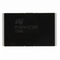
M29DW323DB70N6F NUMONYX, M29DW323DB70N6F Datasheet - Page 18

M29DW323DB70N6F
Manufacturer Part Number
M29DW323DB70N6F
Description
IC FLASH 32MBIT 70NS 48TSOP
Manufacturer
NUMONYX
Series
Axcell™r
Datasheet
1.M29DW323DT70ZE6F.pdf
(51 pages)
Specifications of M29DW323DB70N6F
Format - Memory
FLASH
Memory Type
FLASH - Nor
Memory Size
32M (4Mx8, 2Mx16)
Speed
70ns
Interface
Parallel
Voltage - Supply
2.7 V ~ 3.6 V
Operating Temperature
-40°C ~ 85°C
Package / Case
48-TSOP
Package
48TSOP
Cell Type
NOR
Density
32 Mb
Architecture
Sectored
Block Organization
Asymmetrical
Location Of Boot Block
Bottom
Typical Operating Supply Voltage
3|3.3 V
Sector Size
8KByte x 8|64KByte x 63
Timing Type
Asynchronous
Interface Type
Parallel
Lead Free Status / RoHS Status
Lead free / RoHS Compliant
M29DW323DT, M29DW323DB
Erase Resume Command
The Erase Resume command must be used to re-
start the Program/Erase Controller after an Erase
Suspend. The device must be in Read Array mode
before the Resume command will be accepted. An
erase can be suspended and resumed more than
once.
Enter Extended Block Command
The M29DW323D has an extra 64KByte block
(Extended Block) that can only be accessed using
the Enter Extended Block command. Three Bus
write cycles are required to issue the Extended
Block command. Once the command has been is-
sued the device enters Extended Block mode
where all Bus Read or Program operations to the
Boot Block addresses access the Extended Block.
The Extended Block (with the same address as
the boot block) cannot be erased, and can be
treated as one-time programmable (OTP) memo-
ry. In Extended Block mode the Boot Blocks are
not accessible. In Extended Block mode dual op-
erations are possible, with the Extended Block
Table 5. Commands, 16-bit mode, BYTE = V
Note: X Don’t Care, PA Program Address, PD Program Data, BA Any address in the Block, BKA Bank Address. All values in the table are in
18/51
Read/Reset
Auto Select
Program
Double Word Program
Unlock Bypass
Unlock Bypass
Program
Unlock Bypass Reset
Chip Erase
Block Erase
Erase Suspend
Erase Resume
Read CFI Query
Enter Extended Block
Exit Extended Block
hexadecimal.
The Command Interface only uses A–1, A0-A10 and DQ0-DQ7 to verify the commands; A11-A20, DQ8-DQ14 and DQ15 are Don’t
Care. DQ15A–1 is A–1 when BYTE is V
Command
6+
1
3
3
4
3
3
2
2
6
1
1
1
3
4
Addr Data Addr Data
BKA
BKA
555
555
555
555
555
555
555
555
555
55
X
X
X
1st
IL
AA
AA
AA
AA
AA
AA
AA
AA
F0
A0
B0
50
90
30
98
or DQ15 when BYTE is V
2AA
2AA
2AA
2AA
2AA
2AA
2AA
2AA
PA0
PA
X
2nd
IH
PD0
PD
55
55
55
55
00
55
55
55
55
(BKA)
Addr
PA1
555
555
555
555
555
555
555
mapped in Bank A. When in Extended Block
mode, Erase Commands in Bank A are not al-
lowed.
To exit from the Extended Block mode the Exit Ex-
tended Block command must be issued.
The Extended Block can be protected, however
once protected the protection cannot be undone.
Exit Extended Block Command
The Exit Extended Block command is used to exit
from the Extended Block mode and return the de-
vice to Read mode. Four Bus Write operations are
required to issue the command.
Block Protect and Chip Unprotect Commands
Groups of blocks can be protected against acci-
dental Program or Erase. The Protection Groups
are shown in
Block Addresses. The whole chip can be unpro-
tected to allow the data inside the blocks to be
changed. Block Protect and Chip Unprotect oper-
ations are described in
X
Bus Write Operations
IH
.
3rd
Data Addr Data Addr Data Addr Data
PD1
F0
A0
90
20
80
80
88
90
555
555
PA
X
APPENDIX
4th
PD
AA
AA
00
APPENDIX D.
2AA
2AA
A., Tables
5th
55
55
23
555
BA
and 24,
6th
10
30


