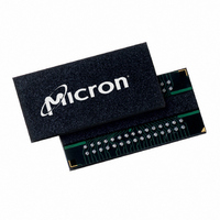
MT47H128M4B6-3:D TR Micron Technology Inc, MT47H128M4B6-3:D TR Datasheet - Page 7

MT47H128M4B6-3:D TR
Manufacturer Part Number
MT47H128M4B6-3:D TR
Description
IC DDR2 SDRAM 512MBIT 3NS 60FBGA
Manufacturer
Micron Technology Inc
Datasheet
1.MT47H128M4BT-37EA_TR.pdf
(129 pages)
Specifications of MT47H128M4B6-3:D TR
Format - Memory
RAM
Memory Type
DDR2 SDRAM
Memory Size
512M (128Mx4)
Speed
3ns
Interface
Parallel
Voltage - Supply
1.7 V ~ 1.9 V
Operating Temperature
0°C ~ 85°C
Package / Case
60-FBGA
Lead Free Status / RoHS Status
Lead free / RoHS Compliant
Other names
557-1291-2
MT47H128M4B6-3:D TR
MT47H128M4B6-3:D TR
512Mb: x4, x8, x16 DDR2 SDRAM
Figure 51: Bank Read – Without Auto Precharge ............................................................................................. 95
Figure 52: Bank Read – with Auto Precharge ................................................................................................... 96
t
t
Figure 53: x4, x8 Data Output Timing –
DQSQ,
QH, and Data Valid Window .................................................. 97
t
t
Figure 54: x16 Data Output Timing –
DQSQ,
QH, and Data Valid Window ...................................................... 98
t
t
Figure 55: Data Output Timing –
AC and
DQSCK .......................................................................................... 99
Figure 56: Write Burst ................................................................................................................................... 101
Figure 57: Consecutive WRITE-to-WRITE ...................................................................................................... 102
Figure 58: Nonconsecutive WRITE-to-WRITE ................................................................................................ 102
Figure 59: WRITE Interrupted by WRITE ....................................................................................................... 103
Figure 60: WRITE-to-READ ........................................................................................................................... 104
Figure 61: WRITE-to-PRECHARGE ................................................................................................................ 105
Figure 62: Bank Write – Without Auto Precharge ............................................................................................ 106
Figure 63: Bank Write – with Auto Precharge ................................................................................................. 107
Figure 64: WRITE – DM Operation ................................................................................................................ 108
Figure 65: Data Input Timing ........................................................................................................................ 109
Figure 66: Refresh Mode ............................................................................................................................... 110
Figure 67: Self Refresh .................................................................................................................................. 112
Figure 68: Power-Down ................................................................................................................................ 114
Figure 69: READ-to-Power-Down or Self Refresh Entry .................................................................................. 116
Figure 70: READ with Auto Precharge-to-Power-Down or Self Refresh Entry .................................................. 116
Figure 71: WRITE-to-Power-Down or Self Refresh Entry ................................................................................ 117
Figure 72: WRITE with Auto Precharge-to-Power-Down or Self Refresh Entry ................................................. 117
Figure 73: REFRESH Command-to-Power-Down Entry ................................................................................. 118
Figure 74: ACTIVATE Command-to-Power-Down Entry ................................................................................ 118
Figure 75: PRECHARGE Command-to-Power-Down Entry ............................................................................ 119
Figure 76: LOAD MODE Command-to-Power-Down Entry ............................................................................ 119
Figure 77: Input Clock Frequency Change During Precharge Power-Down Mode ........................................... 120
Figure 78: RESET Function ........................................................................................................................... 122
Figure 79: ODT Timing for Entering and Exiting Power-Down Mode .............................................................. 124
Figure 80: Timing for MRS Command to ODT Update Delay .......................................................................... 125
Figure 81: ODT Timing for Active or Fast-Exit Power-Down Mode ................................................................. 125
Figure 82: ODT Timing for Slow-Exit or Precharge Power-Down Modes ......................................................... 126
Figure 83: ODT Turn-Off Timings When Entering Power-Down Mode ............................................................ 126
Figure 84: ODT Turn-On Timing When Entering Power-Down Mode ............................................................. 127
Figure 85: ODT Turn-Off Timing When Exiting Power-Down Mode ............................................................... 128
Figure 86: ODT Turn-On Timing When Exiting Power-Down Mode ................................................................ 129
7
PDF: 09005aef82f1e6e2
Micron Technology, Inc. reserves the right to change products or specifications without notice.
512MbDDR2.pdf - Rev. O 7/09 EN
©2004 Micron Technology, Inc. All rights reserved.


