DS1251YP-70IND+ Maxim Integrated Products, DS1251YP-70IND+ Datasheet - Page 6
DS1251YP-70IND+
Manufacturer Part Number
DS1251YP-70IND+
Description
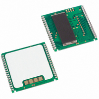
IC NVSRAM 4MBIT 70NS 34PCM
Manufacturer
Maxim Integrated Products
Datasheet
1.DS1251Y-70.pdf
(21 pages)
Specifications of DS1251YP-70IND+
Format - Memory
RAM
Memory Type
NVSRAM (Non-Volatile SRAM)
Memory Size
4M (512K x 8)
Speed
70ns
Interface
Parallel
Voltage - Supply
4.5 V ~ 5.5 V
Operating Temperature
-40°C ~ 85°C
Package / Case
34-PowerCap™ Module
Lead Free Status / RoHS Status
Lead free / RoHS Compliant


DS1251/DS1251P
PHANTOM CLOCK REGISTER DEFINITION Figure 2
AM/PM/12/24 MODE
Bit 7 of the hours register is defined as the 12-hour or 24-hour mode-select bit. When high, the 12-hour
mode is selected. In the 12-hour mode, bit 5 is the AM/PM bit with logic high being PM. In the 24-hour
mode, bit 5 is the second 10-hour bit (20–23 hours).
OSCILLATOR AND RESET BITS
Bits 4 and 5 of the day register are used to control the
and oscillator functions. Bit 4 controls the
RST
(pin 1). When the
bit is set to logic 1, the
input pin is ignored. When the
bit is set to
RST
RST
RST
RST
logic 0, a low input on the
pin will cause the phantom clock to abort data transfer without changing
RST
data in the watch registers. Bit 5 controls the oscillator. When set to logic 1, the oscillator is off. When set
to logic 0, the oscillator turns on and the watch becomes operational. These bits are shipped from the
factory set to a logic 1.
ZERO BITS
Registers 1, 2, 3, 4, 5, and 6 contain one or more bits, which will always read logic 0. When writing these
locations, either a logic 1 or 0 is acceptable.
6 of 21
Related parts for DS1251YP-70IND+
Image
Part Number
Description
Manufacturer
Datasheet
Request
R

Part Number:
Description:
IC NVSRAM 4MBIT 70NS 34PCM
Manufacturer:
Maxim Integrated Products
Datasheet:
Part Number:
Description:
IC NVSRAM 4MBIT 70NS 34PCM
Manufacturer:
Maxim Integrated Products
Datasheet:

Part Number:
Description:
Real Time Clock
Manufacturer:
Maxim Integrated Products
Datasheet:

Part Number:
Description:
The DS1251 4096K NV SRAM with Phantom Clock is a fully static nonvolatile RAM (organized as 512K words by 8 bits) with a built-in real-time clock
Manufacturer:
Maxim
Datasheet:
Part Number:
Description:
Real Time Clock 4096K NV SRAM w/Phantom Clock
Manufacturer:
Maxim Integrated
Datasheet:
Part Number:
Description:
Real Time Clock 4096K NV SRAM w/Phantom Clock
Manufacturer:
Maxim Integrated
Datasheet:
Part Number:
Description:
MAX7528KCWPMaxim Integrated Products [CMOS Dual 8-Bit Buffered Multiplying DACs]
Manufacturer:
Maxim Integrated Products
Datasheet:
Part Number:
Description:
Single +5V, fully integrated, 1.25Gbps laser diode driver.
Manufacturer:
Maxim Integrated Products
Datasheet:
Part Number:
Description:
Single +5V, fully integrated, 155Mbps laser diode driver.
Manufacturer:
Maxim Integrated Products
Datasheet:
Part Number:
Description:
VRD11/VRD10, K8 Rev F 2/3/4-Phase PWM Controllers with Integrated Dual MOSFET Drivers
Manufacturer:
Maxim Integrated Products
Datasheet:
Part Number:
Description:
Highly Integrated Level 2 SMBus Battery Chargers
Manufacturer:
Maxim Integrated Products
Datasheet:
Part Number:
Description:
Current Monitor and Accumulator with Integrated Sense Resistor; ; Temperature Range: -40°C to +85°C
Manufacturer:
Maxim Integrated Products
Part Number:
Description:
TSSOP 14/A°/RS-485 Transceivers with Integrated 100O/120O Termination Resis
Manufacturer:
Maxim Integrated Products
Part Number:
Description:
TSSOP 14/A°/RS-485 Transceivers with Integrated 100O/120O Termination Resis
Manufacturer:
Maxim Integrated Products
Part Number:
Description:
QFN 16/A°/AC-DC and DC-DC Peak-Current-Mode Converters with Integrated Step
Manufacturer:
Maxim Integrated Products