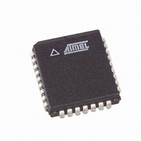
AT27C020-70JC Atmel, AT27C020-70JC Datasheet

AT27C020-70JC
Specifications of AT27C020-70JC
Available stocks
Related parts for AT27C020-70JC
AT27C020-70JC Summary of contents
Page 1
... Any byte can be accessed in less than 55 ns, eliminating the need for speed reducing WAIT states on high perfor- mance microprocessor systems. In read mode, the AT27C020 typically consumes 8 mA. Standby mode supply current is typically less than 10 A. Pin Configurations ...
Page 2
... The AT27C020 is available in a choice of industry standard JEDEC-approved one-time programmable (OTP) plastic PDIP, PLCC, and TSOP packages. All devices feature two- line control (CE, OE) to give designers the flexibility to pre- vent bus contention. With 256K byte storage capability, the AT27C020 allows firmware to be stored reliably and to be accessed by the system without the delays of mass storage media. Atmel’ ...
Page 3
Absolute Maximum Ratings* Temperature Under Bias.......................-55°C to +125°C Storage Temperature............................-65°C to +150°C Voltage on Any Pin with Respect to Ground ............................... -2.0V to +7.0V Voltage on A9 with Respect to Ground ............................ -2.0V to +14.0V V Supply Voltage with PP ...
Page 4
... AT27C020 -90 -12 0°C - 70°C 0°C - 70°C - 85C - 85C 5V 10% 5V 10% Min Max 1.0 (Com., Ind.) 5.0 10 0.3V 100 CC + 0.5V 1 -0.6 0.8 2 0.5 CC 0.4 2 AT27C020 -90 -12 -15 Min Max Min Max Min 90 120 90 120 -15 0°C - 70°C - 85C 5V 10% Units and Max Units ...
Page 5
AC Waveforms for Read Operation Notes: 1. Timing measurement references are 0.8V and 2.0V. Input AC drive levels are 0.45V and 2.4V, unless otherwise specified may be delayed may be delayed up to ...
Page 6
... Programming Waveforms Notes: 1. The Input Timing reference is 0.8V for and t are characteristics of the device but must be accommodated by the programmer. OE DFP 3. When programming the AT27C020, a 0.1 F capacitor is required across V DC Programming Characteristics ± 5° 6.5 ± 0.25V Symbol Parameter I Input Load Current ...
Page 7
... This parameter is only sampled and is not 100% tested. Output Float is defined as the point where data is no longer driven — see timing diagram. 3. Program Pulse width tolerance is 100 s Atmel’s 27C020 Integrated Product Identification Code Codes A0 O7 Manufacturer ...
Page 8
... After the byte verifies properly, the next address is selected until all have been checked then lowered to 5.0V and V PP 5.0V. All bytes are read again and compared with the origi- nal data to determine if the device passes or fails. AT27C020 8 is raised to 6.5V and ...
Page 9
... Wide, Plastic Dual Inline Package (PDIP) 32T 32-Lead, Plastic Thin Small Outline Package (TSOP) Ordering Code 0.1 AT27C020-55JC AT27C020-55PC AT27C020-55TC 0.1 AT27C020-55JI AT27C020-55PI AT27C020-55TI 0.1 AT27C020-70JC AT27C020-70PC AT27C020-70TC 0.1 AT27C020-70JI AT27C020-70PI AT27C020-70TI 0.1 AT27C020-90JC AT27C020-90PC AT27C020-90TC 0.1 AT27C020-90JI AT27C020-90PI AT27C020-90TI 0 ...


