M29W200BB55N1 STMicroelectronics, M29W200BB55N1 Datasheet - Page 5
M29W200BB55N1
Manufacturer Part Number
M29W200BB55N1
Description
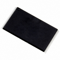
IC FLASH 2MBIT 55NS 48TSOP
Manufacturer
STMicroelectronics
Datasheet
1.M29W200BB55N1.pdf
(22 pages)
Specifications of M29W200BB55N1
Format - Memory
FLASH
Memory Type
FLASH - Nor
Memory Size
2M (256K x 8 or 128K x 16)
Speed
55ns
Interface
Parallel
Voltage - Supply
2.7 V ~ 3.6 V
Operating Temperature
0°C ~ 70°C
Package / Case
48-TSOP
Lead Free Status / RoHS Status
Lead free / RoHS Compliant
Available stocks
Company
Part Number
Manufacturer
Quantity
Price


BUS OPERATIONS
There are five standard bus operations that control
the device. These are Bus Read, Bus Write, Out-
put Disable, Standby and Automatic Standby. See
Tables 5 and 6, Bus Operations, for a summary.
Typically glitches of less than 5ns on Chip Enable
or Write Enable are ignored by the memory and do
not affect bus operations.
Bus Read. Bus Read operations read from the
memory cells, or specific registers in the Com-
mand Interface. A valid Bus Read operation in-
volves setting the desired address on the Address
Inputs, applying a Low signal, V
and Output Enable and keeping Write Enable
High, V
value, see Figure 8, Read Mode AC Waveforms,
and Table 14, Read AC Characteristics, for details
of when the output becomes valid.
Bus Write. Bus Write operations write to the
Command Interface. A valid Bus Write operation
begins by setting the desired address on the Ad-
dress Inputs. The Address Inputs are latched by
the Command Interface on the falling edge of Chip
Table 5. Bus Operations, BYTE = V
Note: X = V
Table 6. Bus Operations, BYTE = V
Note: X = V
Bus Read
Bus Write
Output Disable
Standby
Read Manufacturer
Code
Read Device Code
Bus Read
Bus Write
Output Disable
Standby
Read Manufacturer
Code
Read Device Code
Operation
Operation
IH
IL
IL
. The Data Inputs/Outputs will output the
or V
or V
IH
IH
.
.
V
V
V
V
V
V
V
V
V
V
E
X
E
X
IH
IH
IL
IL
IL
IL
IL
IL
IL
IL
V
V
V
V
V
V
V
V
V
V
IL
G
G
X
X
IH
IH
IH
IH
IL
IL
IL
IL
IL
IL
, to Chip Enable
IL
IH
V
V
V
V
V
V
V
V
V
V
W
W
X
X
IH
IH
IH
IH
IH
IH
IH
IH
IL
IL
Cell Address
Command Address
X
X
A0 = V
Others V
A0 = V
Others V
Cell Address
Command Address
X
X
A0 = V
Others V
A0 = V
Others V
DQ15A–1, A0-A16
Address Inputs
Address Inputs
IL
IH
IL
IH
, A1 = V
, A1 = V
, A1 = V
, A1 = V
IL
IL
IL
IL
Enable or Write Enable, whichever occurs last.
The Data Inputs/Outputs are latched by the Com-
mand Interface on the rising edge of Chip Enable
or Write Enable, whichever occurs first. Output En-
able must remain High, V
Write operation. See Figures 9 and 10, Write AC
Waveforms, and Tables 15 and 16, Write AC
Characteristics, for details of the timing require-
ments.
Output Disable. The Data Inputs/Outputs are in
the high impedance state when Output Enable is
High, V
Standby. When Chip Enable is High, V
memory enters Standby mode and the Data In-
puts/Outputs pins are placed in the high-imped-
ance state. To reduce the Supply Current to the
Standby Supply Current, I
be held within V
level see Table 13, DC Characteristics.
During program or erase operations the memory
will continue to use the Program/Erase Supply
Current, I
til the operation completes.
A0-A16
or V
or V
or V
or V
IH
IH
IH
IH
IL
IL
IL
IL
IH
, A9 = V
, A9 = V
, A9 = V
, A9 = V
.
CC3
, for Program or Erase operations un-
ID
ID
ID
ID
CC
,
,
,
,
M29W200BT, M29W200BB
± 0.2V. For the Standby current
DQ14-DQ8
Hi-Z
Hi-Z
Hi-Z
Hi-Z
Hi-Z
Hi-Z
DQ15A–1, DQ14-DQ0
0057h (M29W200BB)
Data Inputs/Outputs
Data Inputs/Outputs
0051h (M29W200BT)
IH
CC2
, during the whole Bus
Data Output
, Chip Enable should
Data Input
0020h
57h (M29W200BB)
51h (M29W200BT)
Hi-Z
Hi-Z
Data Output
Data Input
DQ7-DQ0
Hi-Z
Hi-Z
20h
IH
, the
5/22
Related parts for M29W200BB55N1
Image
Part Number
Description
Manufacturer
Datasheet
Request
R

Part Number:
Description:
STMicroelectronics [RIPPLE-CARRY BINARY COUNTER/DIVIDERS]
Manufacturer:
STMicroelectronics
Datasheet:
Part Number:
Description:
STMicroelectronics [LIQUID-CRYSTAL DISPLAY DRIVERS]
Manufacturer:
STMicroelectronics
Datasheet:

Part Number:
Description:
BOARD EVAL FOR MEMS SENSORS
Manufacturer:
STMicroelectronics
Datasheet:
Part Number:
Description:
NPN TRANSISTOR POWER MODULE
Manufacturer:
STMicroelectronics
Datasheet:
Part Number:
Description:
TURBOSWITCH ULTRA-FAST HIGH VOLTAGE DIODE
Manufacturer:
STMicroelectronics
Datasheet:
Part Number:
Description:
Manufacturer:
STMicroelectronics
Datasheet:
Part Number:
Description:
DIODE / SCR MODULE
Manufacturer:
STMicroelectronics
Datasheet:
Part Number:
Description:
DIODE / SCR MODULE
Manufacturer:
STMicroelectronics
Datasheet:
Part Number:
Description:
Search -----> STE16N100
Manufacturer:
STMicroelectronics
Datasheet:
Part Number:
Description:
Search ---> STE53NA50
Manufacturer:
STMicroelectronics
Datasheet:
Part Number:
Description:
NPN Transistor Power Module
Manufacturer:
STMicroelectronics
Datasheet:
Part Number:
Description:
DIODE / SCR MODULE
Manufacturer:
STMicroelectronics
Datasheet: