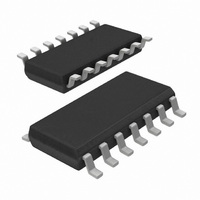
TEA1533AT/N1,518 NXP Semiconductors, TEA1533AT/N1,518 Datasheet - Page 13

TEA1533AT/N1,518
Manufacturer Part Number
TEA1533AT/N1,518
Description
IC CTRLR SMPS GREEN OVP 14SOIC
Manufacturer
NXP Semiconductors
Series
GreenChip™ IIr
Datasheet
1.TEA1533ATN1518.pdf
(24 pages)
Specifications of TEA1533AT/N1,518
Package / Case
14-SOIC (0.154", 3.90mm Width)
Output Isolation
Isolated
Frequency Range
25 ~ 175kHz
Voltage - Input
8.7 ~ 20 V
Voltage - Output
650V
Power (watts)
750mW
Operating Temperature
-20°C ~ 145°C
Mounting Style
SMD/SMT
Lead Free Status / RoHS Status
Lead free / RoHS Compliant
Lead Free Status / RoHS Status
Lead free / RoHS Compliant, Lead free / RoHS Compliant
Other names
568-2338-2
935270018518
TEA1533ATD-T
935270018518
TEA1533ATD-T
Available stocks
Company
Part Number
Manufacturer
Quantity
Price
Company:
Part Number:
TEA1533AT/N1,518
Manufacturer:
Maxim
Quantity:
51
Philips Semiconductors
CHARACTERISTICS
T
the IC; unless otherwise specified.
2002 Aug 23
Start-up current source (pin DRAIN)
I
BV
M-level
Supply voltage management (pin V
V
V
V
I
I
I
I
I
Demagnetization management (pin DEM)
V
I
V
V
t
Pulse width modulator
t
t
Oscillator
f
f
V
amb
DRAIN
CC(h)
CC(l)
CC(restart)
CC(oper)
CC(burstmode)
prot(DEM)
suppr
on(min)
on(max)
osc(l)
osc(h)
CC(start)
CC(UVLO)
CC(hys)
th(DEM)
clamp(DEM)(neg)
clamp(DEM)(pos)
vco(start)
GreenChip
SYMBOL
DSS
= 25 C; V
CC
supply current drawn from
pin DRAIN
breakdown voltage
mains-dependent operation
enabling level
start-up voltage on V
under voltage lock-out on V
hysteresis voltage on V
pin V
pin V
pin V
supply current under normal
operation
supply current while not switching
demagnetization comparator
threshold voltage on pin DEM
protection current on pin DEM
negative clamp voltage on
pin DEM
positive clamp voltage on
pin DEM
suppression of transformer
ringing at start of secondary
stroke
minimum on-time
maximum on-time
oscillator low fixed frequency
oscillator high fixed frequency
peak voltage on pin I
frequency reduction starts
= 15 V; all voltages are measured with respect to ground; currents are positive when flowing into
TM
II SMPS control IC
CC
CC
CC
charging current, high
charging current, low
restart current
PARAMETER
CC
sense
CC
)
CC
, where
CC
V
with auxiliary supply;
V
V
V
V
3 V < V
V
V
no load on pin DRIVER
V
I
I
latched
V
V
see Figs 6 and 7
DEM
DEM
CC
DRAIN
CC(start)
DRAIN
DRAIN
DRAIN
CC(UVLO)
DEM
CTRL
CTRL
= 0 V; V
13
= 150 A
= 250 A
= 50 mV
CONDITIONS
> 1.5 V
< 1 V
> 100 V
> 100 V; V
> 100 V;
CC
> 100 V;
< V
< V
V
CC(UVLO)
DRAIN
CC
CC(UVLO)
< V
CC
> 100 V
CC(start)
< 3V
TEA1533T; TEA1533AT
1.0
650
60
10.3
8.1
2.0
1.1
50
0.5
1.1
40
20
145
MIN.
1.2
1.2
650
50
0.5
(1)
1.2
100
11
8.7
2.3
1.3
0.85
100
0.7
1.5
t
50
25
175
VCO
leb
1
0.75
550
0.25
TYP.
1
Product specification
1.4
300
100
11.7
9.3
2.6
1.5
150
0.9
1.9
60
30
205
MAX.
0.8
0.45
450
10
0.05
mA
V
V
V
V
V
mA
mA
mA
mA
mV
nA
V
V
ns
kHz
kHz
mV
UNIT
A
A
s
s


