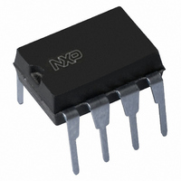
TEA1520P/N2,112 NXP Semiconductors, TEA1520P/N2,112 Datasheet - Page 10

TEA1520P/N2,112
Manufacturer Part Number
TEA1520P/N2,112
Description
IC CTRLR SMPS OVP UVLO HV 8DIP
Manufacturer
NXP Semiconductors
Series
STARplug™r
Specifications of TEA1520P/N2,112
Package / Case
8-DIP (0.300", 7.62mm)
Output Isolation
Isolated
Frequency Range
10 ~ 200kHz
Voltage - Input
7.5 ~ 40 V
Voltage - Output
650V
Power (watts)
1W
Operating Temperature
-40°C ~ 145°C
Output Power
30 W
Input Voltage
2.5 V
Switching Frequency
550 KHz
Operating Temperature Range
- 20 C to + 85 C
Mounting Style
Through Hole
Duty Cycle (max)
75 %
Lead Free Status / RoHS Status
Lead free / RoHS Compliant
For Use With
568-4326 - KIT DEMO STARPLUG BRONCO II
Lead Free Status / Rohs Status
Lead free / RoHS Compliant
Other names
568-2439-5
935269962112
TEA1520P/N2
TEA1520PN
TEA1520PN
935269962112
TEA1520P/N2
TEA1520PN
TEA1520PN
NXP Semiconductors
10. Thermal characteristics
11. Characteristics
TEA152X
Product data sheet
Table 5.
[1]
Table 6.
T
positive when flowing into the IC; unless otherwise specified.
Symbol
R
Symbol
Supply
I
I
I
V
V
I
Pulse-width modulator
δ
δ
SOPS
V
t
RC oscillator
V
V
t
f
Duty factor regulator: pin REG
V
G
V
CC(oper)
CC(startup)
CC(ch)
drain
sup(xfmr_ring)
ch(RC)
osc
amb
min
max
CC(startup)
CC(stop)
det(demag)
RC(min)
RC(max)
REG
clamp(REG)
th(j-a)
v
Thermal resistance R
printed-circuit board. See the TEA152x application note for details.
= 25
°
C; no overtemperature; all voltages are measured with respect to ground; currents are
Parameter
thermal resistance from junction to ambient in free air
Thermal characteristics
Characteristics
DIP8 package
SO14 package
Parameter
operating supply current
start-up supply current
charge supply current
start-up supply voltage
stop supply voltage
current on pin DRAIN
minimum duty factor
maximum duty cycle
demagnetization detection
voltage
transformer ringing
suppression time
minimum voltage on pin RC
maximum voltage on pin RC
charge time on pin RC
oscillator frequency
voltage on pin REG
voltage gain
clamp voltage on pin REG
All information provided in this document is subject to legal disclaimers.
Rev. 04 — 14 September 2010
th(j-a)
can be lower when the GND pins are connected to sufficient copper area on the
Conditions
normal operation
start-up
V
undervoltage lockout
V
f = 100 kHz
start of 2
error amplifier
I
REG
drain
drain
no auxiliary supply
with auxiliary
supply
= 6 mA
> 60 V
> 60 V
nd
Conditions
stroke
SMPS ICs for low-power systems
Min
-
-
−6
9
7.0
-
-
-
-
50
1.0
60
2.4
-
10
2.4
-
-
TEA152x
© NXP B.V. 2010. All rights reserved.
[1]
Typ
1.3
180
−4
9.5
7.5
1.5
30
0
75
100
1.5
75
2.5
1
100
2.5
20
-
Typ
100
91
Max
1.9
400
−3
10
8.0
2
125
-
-
150
2.0
90
2.6
-
200
2.6
-
7.5
Unit
K/W
K/W
10 of 20
Unit
mA
μA
mA
V
V
mA
μA
%
%
mV
μs
mV
V
μs
kHz
V
dB
V


