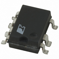
TNY377GN-TL Power Integrations, TNY377GN-TL Datasheet - Page 5

TNY377GN-TL
Manufacturer Part Number
TNY377GN-TL
Description
IC OFFLINE SWIT UVLO 8SMD
Manufacturer
Power Integrations
Series
TinySwitch®-PKr
Type
Off Line Switcherr
Datasheet
1.TNY376PN.pdf
(22 pages)
Specifications of TNY377GN-TL
Output Isolation
Isolated
Frequency Range
132 ~ 280kHz
Voltage - Output
700V
Power (watts)
28W
Operating Temperature
-40°C ~ 150°C
Package / Case
8-SMD Gull Wing, 7 Leads
Lead Free Status / RoHS Status
Lead free / RoHS Compliant
Enable Function
TinySwitch-PK senses the EN/UV pin to determine whether or
not to proceed with the next switching cycle. The sequence of
cycles is used to determine the current limit. Once a cycle is
started, it always completes the cycle (even when the EN/UV
pin changes state halfway through the cycle). This operation
results in a power supply in which the output voltage ripple is
determined by the output capacitor, amount of energy per
switch cycle, and the delay of the feedback.
Figure 6.
Figure 7.
www.powerint.com
DC
V
I
DC
V
CLOCK
I
CLOCK
DRAIN
DRAIN
DRAIN
DRAIN
MAX
MAX
V
V
EN
EN
Operation at Near Maximum Loading (f
Operation at Moderately Heavy Loading (f
OSC
OSC
264 kHz).
264 kHz).
PI-2749-082305
PI-2667-082305
The EN/UV pin signal is generated on the secondary by
comparing the power supply output voltage with a reference
voltage. The EN/UV pin signal is high when the power supply
output voltage is less than the reference voltage. In a typical
implementation, the EN/UV pin is driven by an optocoupler.
The collector of the optocoupler transistor is connected to the
EN/UV pin, and the emitter is connected to the SOURCE pin.
The optocoupler LED is connected in series with a Zener diode
across the DC output voltage to be regulated. When the output
voltage exceeds the target regulation voltage level (optocoupler
LED voltage drop plus Zener voltage), the optocoupler LED will
start to conduct, pulling the EN/UV pin low. The Zener diode
can be replaced by a TL431 reference circuit for improved
accuracy.
ON/OFF Operation with Current Limit State Machine
The internal clock of the TinySwitch-PK runs at all times. At the
beginning of each clock cycle, it samples the EN/UV pin to
decide whether or not to implement a switch cycle, and based
on the sequence of samples over multiple cycles, it determines
the appropriate current limit. At high loads, the state machine
sets the current limit to its highest value. With TinySwitch-PK,
when the state machine sets the current limit to its highest
value, the oscillator frequency is also doubled, providing the
unique peak mode operation. At lighter loads, the state
machine sets the current limit to reduced values. At these lower
current limit levels, the oscillator frequency returns to the
standard value.
At near maximum load, TinySwitch-PK will conduct during
nearly all of its clock cycles (Figure 6). At slightly lower load, it
will “skip” additional cycles in order to maintain voltage
regulation at the power supply output (Figure 7). At medium
loads, more cycles will be skipped, the current limit will be
Figure 8.
DC
V
I
CLOCK
DRAIN
DRAIN
MAX
V
EN
Operation at Medium Loading (f
OSC
TNY375-380
132 kHz).
PI-4540-050407
Rev. C 07/09
5


